This is a DIY reader for 8-bit (9-hole) vintage paper tapes. I started working on this because I couldn't find any DIY solution online that would allow for fully automated tape playback. Hopefully someone will find this interesting/useful!

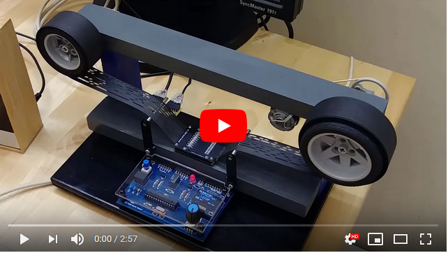
You can watch a short demo video of the reader connected to an Altair 8800 emulator here:
When I started with this project, constructing the reader head was the most uncertain aspect. I found some other DIY attempts on the web but none seemed ideal. I wanted to use miniature photo-transistors that could fit on a 0.1" grid (to match the .1" spacing of the paper tape holes). I found the Kingbright AM2520P3BT03 IR phototransistors and wavelength-matched ON Semiconductor QEB363ZR IR LEDs. Initial tests with these mounted on a perfboard were very promising, so I made two matched PCBs (emitter and sensor) that can be sandwiched together to form the reader head:


All resistors on the two boards are 0805 SMD resistors. Resistors on the sensor board (with the photo-transistors) are 1k Ohm. Resistors on the emitter board (with the LEDs) are 470 Ohm except for the index-hole LED which uses 330 Ohm (to make the LED brighter because the holes are smaller). Note that these resistor values were chosen for a 3.3V supply voltage.
Gerber files for both PCBs are in the schematics subdirectory.
As is, the signals from the reader head can be directly attached to the digital inputs of any 3.3V microprocessor and should give clear and stable readings. I have tested the reader with black as well as pink paper tape.
In addition to the reader head I also made a main board which does the following:
- Read the (parallel) data from the reader head and send it out on a serial connection
- Control a motor to automatically run the tape at proper speed given the serial transmission rate
- Provide a menu system for setting a variety of parameters

The board is centered around an Atmega328p running at 3.3V. The schematic, PCB layout and Gerber files are in the schematics subdirectory.
To display and navigate the menu system I used a 128x64 OLED display paired with a standard rotary encoder. Both are easy to find on Ebay, for the OLED make sure that the pinout matches that on the board (many different versions exist). The relay on the board is a Omron G5V-1-DC3 and the voltage regulator is a Recom R-78E3.3-1.0. Note that the crystal must be 8MHz which is the maximum clock speed for an Atmega328P running at 3.3V. All other components are standard and should be labeled in the schematics
There are two serial connections, one labeled "Terminal" and one labeled "Computer". This allows the tape reader to be placed between a terminal and a computer. As long as the reader is not actively running, all data is just passed between the "Terminal" and "Computer" serial ports. When the reader is running, it disconnects the terminal input and sends the tape data out to the computer instead. The TX LED is on while the reader is transmitting.
To program the Atmega328p you need to use a separate programmer. There is no ICSP header or serial connection for programming on the board as the corresponding pinsare already in use otherwise. I personally use a MiniPro but you can also just use an Arduino Uno. When compiling the sketch, make sure to set the board as "Arduino Pro or Pro Mini" and processor as "Atmega328P 3.3V 8MHz".
The reader head and main board can be used without a motor by manually pulling the tape, however one of the main features is the ability to control the motor as seen in the video.
Motor power is varied using PWM. The PWM setting gets adjusted by a PID controller whose parameters can be easily set using the menu system (see below).
Note that there is no direct connection built into the firmware between the serial transmission speed and motor speed. Instead, the PID controller varies the motor power to achieve and hold a 10% fill state of the internal transmit buffer. Since PID parameters and basic motor parameters are configurable via the menu system, a variety of (DC) motors should be supported.
I just used a motor that I had salvaged from an old printer and adjusted the parameters by experimentation.
The menu system is operated by the rotary controller. The current item is marked by a ">" symbol and rotating will move between items and screens. Generally, a short button push on an item advances it to its next setting (e.g. next greater baud rate). A long button push puts it into "modify" mode where rotating the controller changes the setting. Exit "modify" mode via a short button push.

The first (and main) menu screen. The three items here (PLAY, PLAY+LDL, FFWD) are not settings but actions:
- A short push on PLAY will start playing the tape. Push again to stop playing. Play stops automatically if no index hole is seen within 2 seconds after starting or 1 second while running.
- A short push on PLAY+LDL starts playing with line delay. Line delay causes the reader to pause for a configurable amout of time (see second screen) after sending a NEWLINE character. This can be necessary if the receiving computer needs extra time to process a newline.
- A short push on FFWD will start fast-forwarding the tape. It just runs the motor at full speed until another push exists fast forward mode.
- A long push on either PLAY or PLAY+LDL is a shortcut to FFWD
- A long push on FFWD enters a test mode. In this mode the display shows the current state of all data holes (index hole is marked with a "^"). Rotating the controller adjusts motor power between 0 and 255. A short push exits test mode.
The bottom row shows the currently selected serial parameters and characters-per-second setting.

This screen configures transmission parameters:
- The CPS setting specifies a maximum characters-per-second setting. If this is set to less than what the serial baud rate allows the reader will pause between sending characters so as to not exceed the CPS setting.
- The LDL setting specifies the line delay in milliseconds (see PLAY+LDL above)
- The SER setting specifies serial parameters. Possible baud rates range from 55-115200. Number of data bits can be 5-8. Parity can be even, odd or none and one or two stop bits are supported.

This screen configures basic motor parameters:
- Set the MIN setting to the minimum power required to keep the motor running. You can experiment with this in the test mode on the first screen.
- The MAX setting allows to limit the maximum motor power if that is necessary. Setting MAX to 0 will put the reader into manual mode, where the firmware assumes you will be pulling the tape manually.
- The INI setting limits the initial motor power which can be necessary to avoid immediately overflowing the send buffer when starting to read.

This screen configures the PID controller parameters. The firmware uses the Arduino PID Controller library. The values specified here are the parameters to the SetTunings() function in steps of 1/100. For example, setting P=10,I=20,D=15 is equivalent to calling SetTunings(0.1,0.2,0.15).

This configures statistics display and COMP mode.
If STAT is set to Y then after reading a tape and finishing to send the data, the reader will show a statistics sreen, displaying CHR (number of characters sent), SEC (number of seconds used to send) and CPS (characters per second) information.
The COMP (compare mode) item is visible only if "#define COMPARE_PROG_SET" in the firmware is set to 1 or 2. If so, the compiler will integrate images of certain files (e.g. 4k BASIC, for details see the bottom of the PaperTapeReader.ino file). You can then select one of these files here. The reader will compare any data read from the tape to the stored data and immediately stop and show an error if a difference is found.
I kept the mechanical construction simple, just using 1x2s and plywood. I am still using the Lego axles and wheels for spools from my first prototype because I haven't found a solution that works better than that setup. If anybody knows where to get small-ish 1" wide plastic spools for paper tape then please let me know!
The two paper guides you can see in the picture at the top of the page are useful when running at lower speeds where motor power regulates up and down. They introduce some drag that stops the tape from flapping around when the motor regulates down. They are not needed when running at full speed.