http:https://chaffneue.github.io/houston/
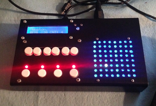
Introducing Houston: A bomb-proof, OSHW multi-master MIDI clock that you can build for about $50 using readily available parts. Make it the center of your live pa rig!
Normally, MIDI devices are slaved to a single master unit, but what if something about that unit crashes or blocks playback for whatever reason? Short answer: "kablammo!" Additionally, if a slave device fails to playback, there's not much recourse for resyncing it to the rest of the performance. In live performance applications, this means that one wrong move on the sequencers means a major interruption of the music.
This device provides a solid performance playback platform that:
- Drastically lowers the chances of a full audio lockup (DAW crashes, PC hardware communication issues, playback-blocking sequencer parameter changes, etc.)
- Automatically stops, rewinds and resyncs up to 4 channels of MIDI slaves back into the mix on the downbeat with a selectable count-in. It dramatically frees up your hands to focus on the mix and switch to new songs unit by unit without interruption.
- 4 independent, hardware UART synchronized midi channels (+/- 0.1 BPM jitter)
- Large, intuitive displays to show all performance parameters including the count-in time, the current tempo and the current measure
- Huge, 12mm OMRON buttons to prevent fat-fingering the controls
- A clear, multicolored beat lamp to help visualize the beat
- Microcontroller based with very limited responsibilities which greatly reduces the risk of a crash during a performance
- Usb powered and programmed
- Open Source Hardware - contribute to making it better or fork it and add your own requirements
- Based on commodity parts freely available on eBay and the ubiqitous Arduino Mega2560 R3 board and development environment
The hardware comprises of 6 modules. I have built these modules using separate perf boards in the prototype.
- The LCD Display (shows tempo and count-in parameters)
- The 8x8 Matrix display (used to show track position)
- The beat lamp display
- The Control surface board
- The Arduino board
- The MIDI IO board
Based on a 1602 (16 char x 2 line) LCD, you really only need to add an adapter board for LCD contrast, since the Arduino bit bangs each pin directly. See the photos below for how I mounted the little breakout board.
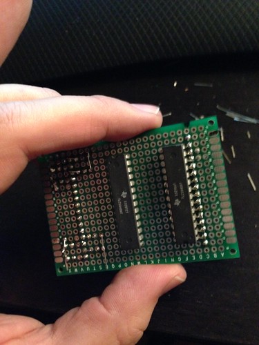
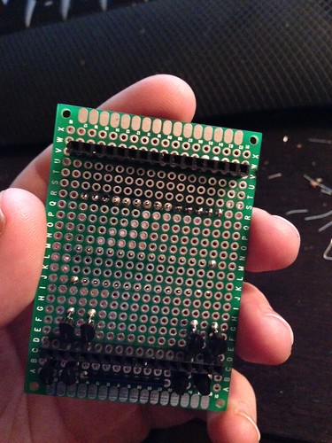
The 8x8 matrix is the trickiest part to build, but it's very hard to mess up. If you've never used this hardware before, you can breadboard it first to ensureall the parts work before soldering them. I used a double sided perf board with vias to build the prototype. This allows me to install the TLC5940 chips on the bottom of the board and the transistors and jumpers on the top side which is neatly sandwiched between the LED matrix when assembled. Note that the 100K pull up resistors on the transistor bases are optional (they reduce switching noise at slower refresh speeds). I didn't use them in the final build due to space constraints.
I used an off the shelf multicolor led mounded to a small pcb and added a 1k current limiting resistor attached to ground. My board had mislabelled the color channeld, so do check the colors are as you expect (you can always fix it in firmware later as long as ground is correct). The model used was KY-016: https://tkkrlab.nl/wiki/Arduino_KY-016_3-color_LED_module.
I build the control surface board using a 7cm x 9cm single sided perf board. The only lesson I have with this is to find a board that isn't quite as cheaply drilled as mine was. Some of the button holes needed a lot of filing to line up bacause the pads and mounting holes were not to the same spec. The switches do have quite chunky leads, so really use a lot of solder on at least two contact pins to make sure nothing comes loose. Dry fit the heck out of the button panel before you drill :)
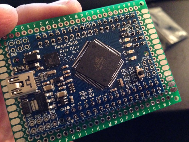
This is a specialized clone that nice and small while retaining a good quality USB programmer. It is readily available on ebay and epalsite for around $10-$15 here http:https://www.epalsite.com/store/meduino-mega2560-r3-pro-mini-board-small-size.html It's compatible with the 2560 R3 and coes with a bootloader already installed. See the firmware instructions below to build and flash this sucker.
I cut down a perfboard to the width measurements shown in the case https://github.com/chaffneue/houston/blob/master/illustrator/houston-back-panel.pdf the board's length isn't too important, but do use a good quality pcb as the flimsy PC mount Din jacks can be hard on pads. Additionally, once mounted, use a zap strap or a few screws behind the midi jack to relieve the strain of inserting the din plugs.
Higher resolution photo album here:
https://www.flickr.com/photos/chaffneue/albums/72157663690274979
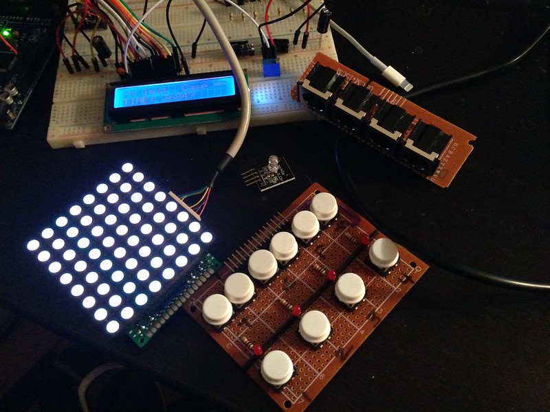
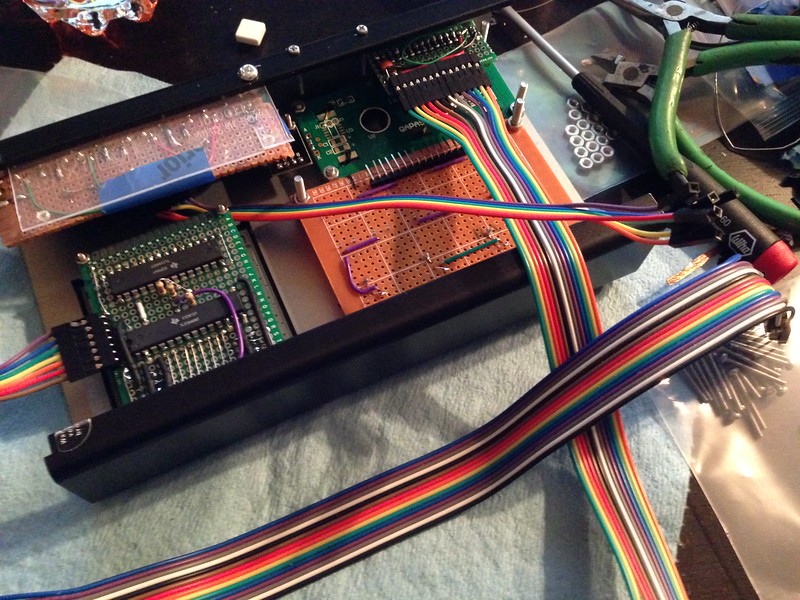
The controls, midi, beat lamp and assembled matrix board. I ended up putting the control panel pin header on the bottom of the board.
The Embeddable Meduino 2560 R3 board
The Matrix board IC, header and transistor placement
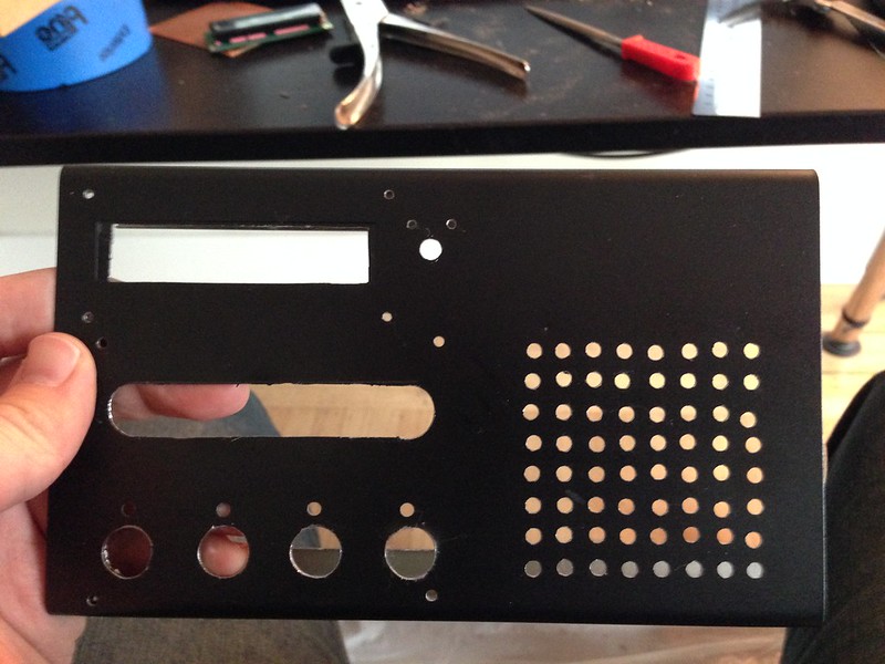
Case details - The prototype is made with a steel 3.5" external HD enclosure which can be had for $10-$20. Punch the holes nice and deep and drill them out carefully. I used a 2,3,5 and 12mm drill bit and a small hobby file set to clean up the burrs. I used a nibbler tool for the LCD and midi jack case openings. The better clamped down the case is while drilling, the better the finish. I used some painters tape to avoid scratching the paint as much as possible.

Cabling - note the orientation of the switch plate and it's header. You can also see the adapter board for the LCD screen on its pin header.
The back panel interface openings

You'll need
- The Github Desktop app https://desktop.github.com/
- The Arduino IDE https://www.arduino.cc/en/Main/Software
The project is buildable from source using the Arduino IDE's built in make file. All you need to do is fork to your own private copy then git clone using Github Desktop (your forks will show up automagically in Github Desktop :)). The nice thing about forking is that you can (and should) change the project with impunity. Want i2c parts? go for it! Different matrix drivers? CV sync? hell yes! do it! The firmware code is documented and separated into discrete tasks, so it should be easy to extend to your live rig's needs.
The {arduino_ide_project_path} is usually in your "My Documents/Arduino" folder on windows and "/path/to/user/Documents/Arduino" on the mac
Fork and clone the firmware sketches into {arduino_ide_project_path} https://github.com/chaffneue/houston
Fork and clone the following libraries in {arduino_ide_project_path}/libraries: https://github.com/chaffneue/DirectIO https://github.com/chaffneue/TaskScheduler https://github.com/chaffneue/LiquidCrystal https://github.com/chaffneue/TLC5940 https://github.com/chaffneue/arduino_midi_library
In the Arduino IDE, load the houston sketch from {arduino_ide_project_path}/houston/houston.ino
Plug your Houston box into USB and choose:
- Board Type: Arduino/Genuino Mega or Mega 2560
- Processor: ATmega2560 (Mega 2560)
- Port: Whatever port was found after plugging in the arduino board
- Programmer: AVRISP mkII
Then click the upload (->) button to build and upload the firmware. It's a good idea to do this as a first step and dry test the components on a breadboard.
And damnit. Have fun!