This program was custom designed to monitor a small (<= 8 PCs) GPU mining farm, all running Claymore's Ethereum miner. This code runs natively on any Raspberry Pi Model B.
To get this up and running for you, you're going to need some hardware:
- 8 channel relay module
- Amazon link: http:https://a.co/bbGLOhq
- Dupont Cables
- Amazon link: http:https://a.co/bmq2vY2
- Optocouplers
- Amazon link: http:https://a.co/0tIJ8TV
- Breadboard
- Amazon link: http:https://a.co/bQdLbd2
- Raspberry Pi Model B
- Amazon link: http:https://a.co/1ZmYYJI
If you need help setting up Raspbian on your Pi, see this tutorial.
First, we're going to remove the jumper on the relay module from the VCC and VCC-JD
pins:
For this particular relay module, the relays need a 5V trigger, but the built in
optocouplers only need a 3.3v trigger, which works out perfectly for the Pi's GPIO
pins. So, to power the relays, we'll go ahead and connect the relay module's VCC-JD
pin to the Pi's +5V pin, pin 2 and the relay module's GND pin to the Pi's ground
pin, pin 6:
TODO
Next, we need to connect the relay module's optocoupler circuit to power and GPIO
inputs. First, we'll want to connect the relay module's VCC connector to the Pi's
+3.3V output, pin 1 and the relay module's other GND connection to another ground
pin on the Pi, pin 9.
TODO
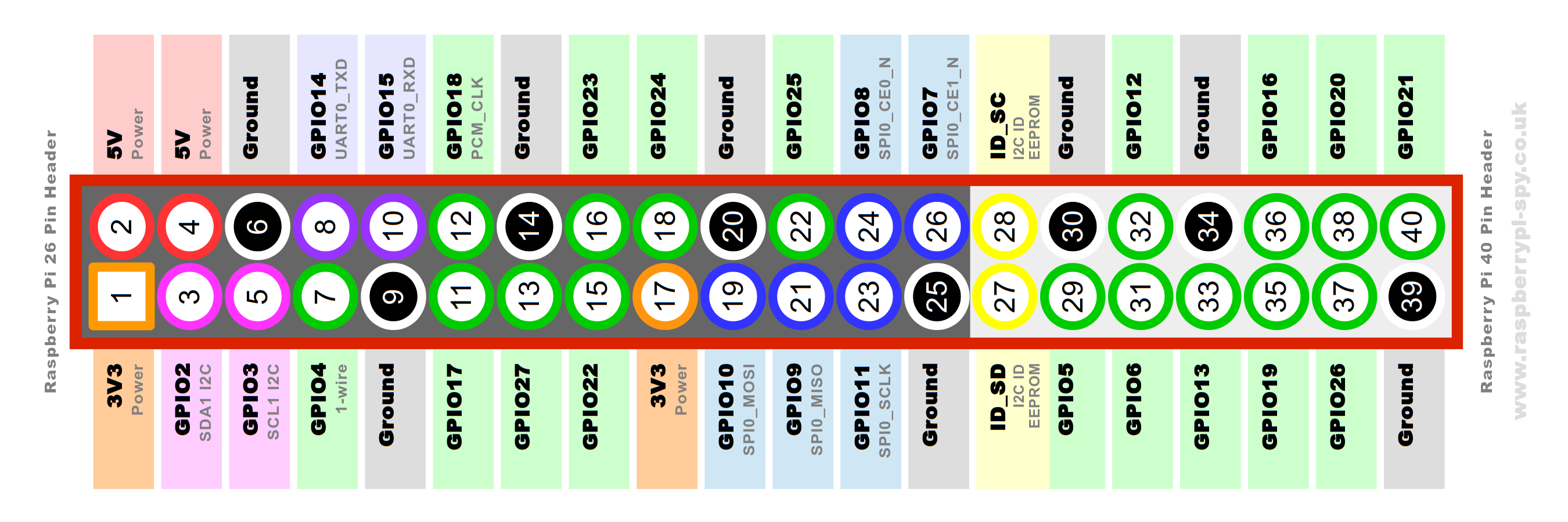
Next, we'll want to connect the relay module's input pins to the Pi's GPIO pins.
Because this program uses board numbering for the GPIO pin positions, the pins are
numbered based on their position in the board. In this image
, you can see each green pin is a GPIO pin. So the first GPIO pin would be Pi pin 7,
the second would be Pi pin 11, and so on.
Next, we need to actually connect up each PC's power switch leads. I used cables terminated with crimped dupont connectors so they could connect directly to the motherboard's power switch pins. Polarity doesn't matter here, but you have to make sure that you connect the leads to the correct relay connections, as shown below:
TODO
For monitoring the powered on/powered off status of our mining rigs, we're going to use the power LED output from each rig's motherboard. The theory is simple, PC power LED outputs -> optocoupler -> GPIO pin.
First, place your optocouplers straddling the middle cutout of your breadboard, making sure they are all oriented the same way. Next, wire your PC's power LED pins to the side of the optocoupler with a dot on it. The dot on top of the chip denotes the anode, or positive lead of the LED inside the optocoupler.
Lastly, wire one lead from the other side of the optocoupler to the ground rail of
the breadboard, and the other side to a GPIO pin on the Pi. The inputs in this program
are setup to use GPIO pins starting from the last one and moving backwards for the
power LED input signals. So, your first rig would use Pi pin 40, your second would
use Pi pin 38, and so on.
Clipart images used from the following sites:
- Red Light:
- Yellow Light:
- Green Light: