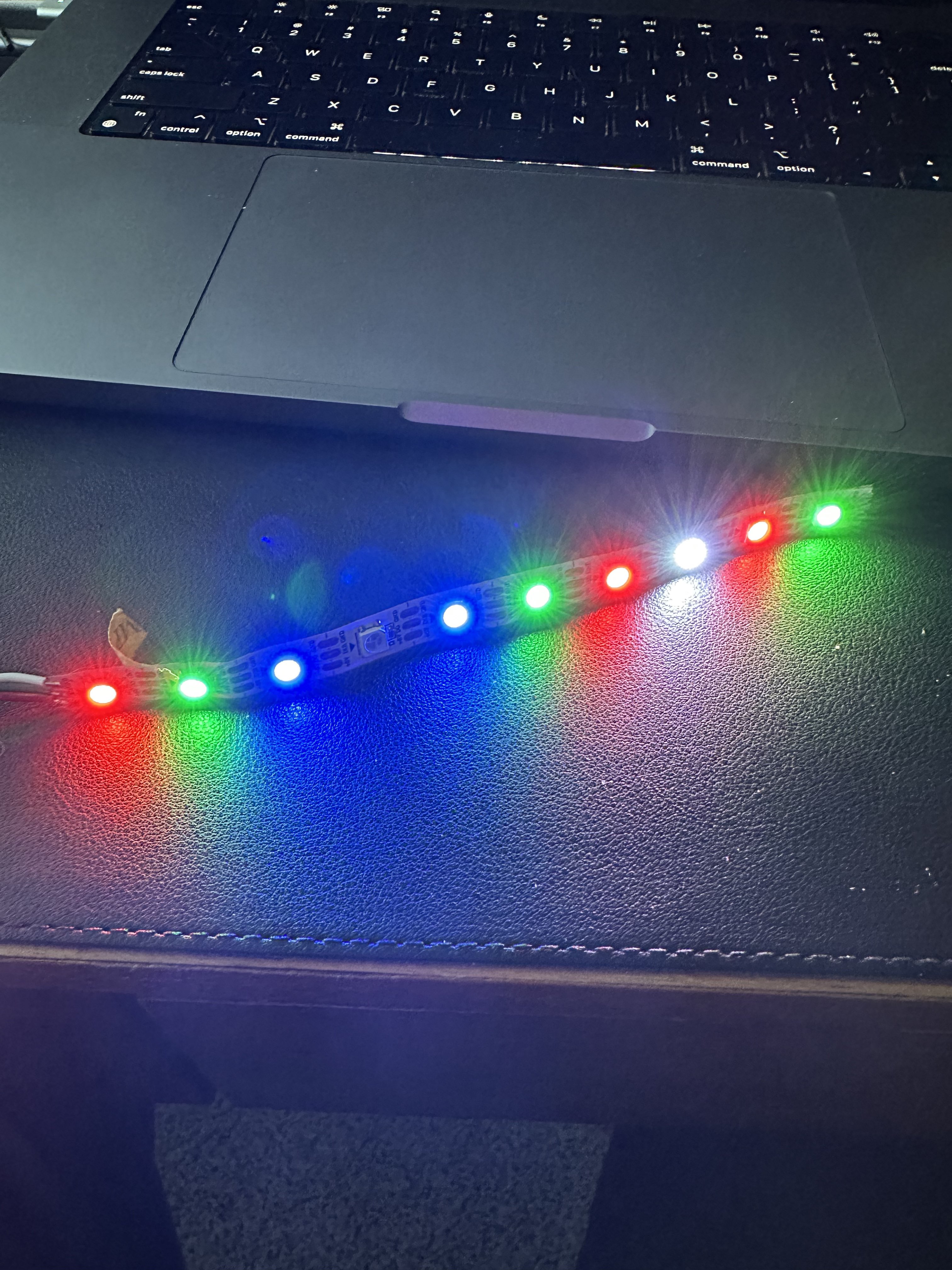
The way the current system works is that you specify the number of LEDs and
the Ws2812 class allocates a byte array to store the encoded data. When you
call the SetColors method, you provide an IEnumerable that produces Color
structures, and then the R, G and B values from that structure are converted
to the on-the-wire representation. The Update method simply does a SPI
transmission of the final encoded data.
| Value | Minimum | Nominal | Maximum |
|---|---|---|---|
| T0H | 200 ns | 350 ns | 500 ns |
| T1H | 550 ns | 700 ns | 850 ns |
| T0L | 650 ns | 800 ns | 950 ns |
| T1L | 450 ns | 600 ns | 750 ns |
| T0H + T0L | 650 ns | 1250 ns | 1850 ns |
| T1H + T1L | 650 ns | 1250 ns | 1850 ns |
| RESET | 50 µs | - | - |
The idea is to use the MOSI signal from the SPI bus to signal the various high and low periods. Some cheats that might be helpful:
- As long as T0H and T1H are in specification, you may be able to get away with T0L and T1L exceeding the maximum (provided that this period is less than the minimum for RESET.) This is naughty, but potentially helpful.
Configuring the SPI data rate to 3 MHz, we can generate pulses that are a multiple of 333 ns. So when we need to send T0H pulses we use a single one bit in the SPI data stream, and to send T1H pulses we use two one bits, yielding pulse widths of about 333 ns and 666 ns respectively.
Taking advantage of the cheat above, we have longer T0L and T1L timings partially due to inter-byte SPI delay (one extra 333 ns interval of low) and partially due to data packing optimization (by encoding a single bit of pixel data as four bits of SPI data, the data conversion is simplified.) We have not seen any situation where the RESET threshold is exceeded. Based on our understanding of the underlying Nuttx SPI implementation, they are not using DMA, but they are keeping the 32 bit FIFO register full, so if there is any condition where the Nuttx SPI write loop is interrupted (chip interrupt for instance), there should not be any data alteration if control returns within 32 * 330 ns.
- Configured frequency (3.2 MHz) doesn't match actual frequency (3 MHz). This is likely because of a mismatch between the master clock speed and the closest divisor.
- After calls to
ISpiBus.Write, the MOSI line is sometimes high, sometimes low. This isn't going to work with my current thinking -- it needs to be low. This is also present in between bytes during the same call toWrite. Here is a forum post that documents the problem. I believe I have managed to avoid it by never setting the MSB in transmitted data.
WS2812 Datasheet (courtesy of Adafruit)
To set up a bench test, connect the power line of a WS2812b strip to the 3v3 pin on the meadow, the ground line to the GND pin on the meadow, and the data line to the COPI pin on the meadow.
Primary Colors
var colors = new Color[] { Color.Red, Color.Green, Color.Blue, Color.Black, Color.Blue, Color.Green, Color.Red, Color.White, Color.Red, Color.Green };

Secondary Colors
var colors = new Color[] { Color.Magenta, Color.LightGreen, Color.SteelBlue, Color.Gray, Color.Brown, Color.Orange, Color.Teal, Color.SeaGreen, Color.SlateBlue, Color.DarkGoldenrod };
