...with USB 2.0 Connectivity for PC simulators
This assembly and firmware has sucessfully been used to control both John Pultorak's Block1 Simulator vers 1.16 in C++ and Ronald Burkey's Block 2 AGC simulators on http:https://www.ibiblio.org/apollo/ Further, the Simulation runs great on Raspberry Pi. I forked the files needed for both simulators. https://github.com/b-wave/virtualagc
I mainly run it on a Rapsberry PI with the intention of embedding the Pi in this chassis. I started a python script that will run the software so I don't have to start the virtual AGC program.... now that is a work in progress...stay tuned
The Teensy 3.2 used in this has a plug in board that contains a Real time clock and navigation sensors. https://www.pjrc.com/store/prop_shield.html Which will mount to the board nicely. I also included a couple of Apollo-themed Processing PDEs in https://github.com/b-wave/uDSKY/tree/master/uDSKY%20IMU that work with this board and it can mount to the uDSKY using stacking header pins.
Why on earth did I do this project? Ultimately, it is a clock. I intend to have a standalone version to do navigation demonstation experiments and become a "moon clock" to track the current position, phase, and distance to the moon - ...in real time!
Its not to scale or even a 1:1 scale model of a DSKY. How I arrived at the scaling was I took the best head-on photo of a DSKY I could find and scaled it to match the smallest descrete LED 7-segment green-ish displays I could find. It turned out that at that scale, the Keys were ~.75" on center, which was nice eand almost exactly 0.75" Square. Also by happy accident the Teensey fits between the top LED Displays. The front panel measurments was about 7.0" x 6.5" so about, but not exactly, half the size of a real DSKY. You will see some early refernces to mini-DSKY Which is the same thing as uDSKY. The whole thing sandwiches nicely together using plexiglas plates - which I will provide laser cut patterns for - and #4 AWG hardware spacers.
The uDSKY assembly is remarkably sturdy and even kind of hefty too. The keys and circuit
boards were attached by small torx head "thread rolling" screws for plastic.
The Torx heads allow for close proximity to components and I think a little easier to install straight.
The hardware I used were surplus and about 2 AWG, ( for a 1/16" pilot hole) and 1/8" long.
I got them on e-bay and i don't have the link, there were 100's of them in a box for a few dollars.
They should be easy to find. I'll update a link if I find a good supplier again.
There are two other circuit boards I am developing. The INDICATOR boards for the LEDs since I used perf boards for this prototype. The POWER REGULATOR board for stand alone operation on 12V dc, and illuminating and controlling the VERB, NOUN, and PROG LEDs and the keyboard backlighting. Since these are a lot of LEDs involved 12V is used for them. These will be controlled the same as the other LEDs using two of the non used DP signals but thru an isolator to control 12V to theses diodes. I also have an idea to use LEDs and some clear plexiglas to simulate the long EL strips between the three registers - but this is still in the idea phase...but the testing is showing promise.
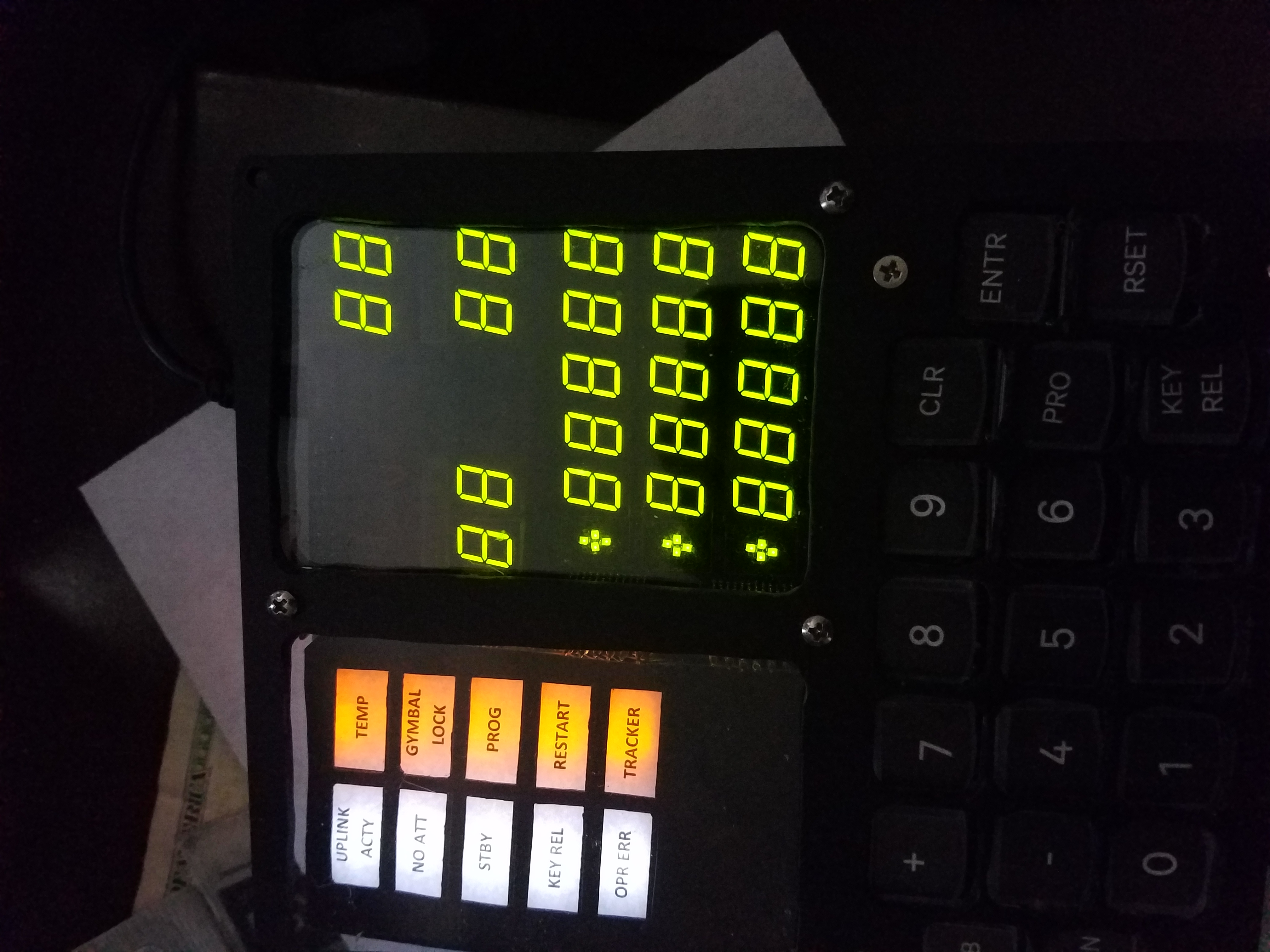
uDSKY in action 9/20/19 on the 50th moonlanding, running on rPI and ran the actual Apollo 11 software (C055), mostly P00 for the entire duration of the flight. This .gif was when they would have been in lunar orbit at 100hrs 38mins or so MET.
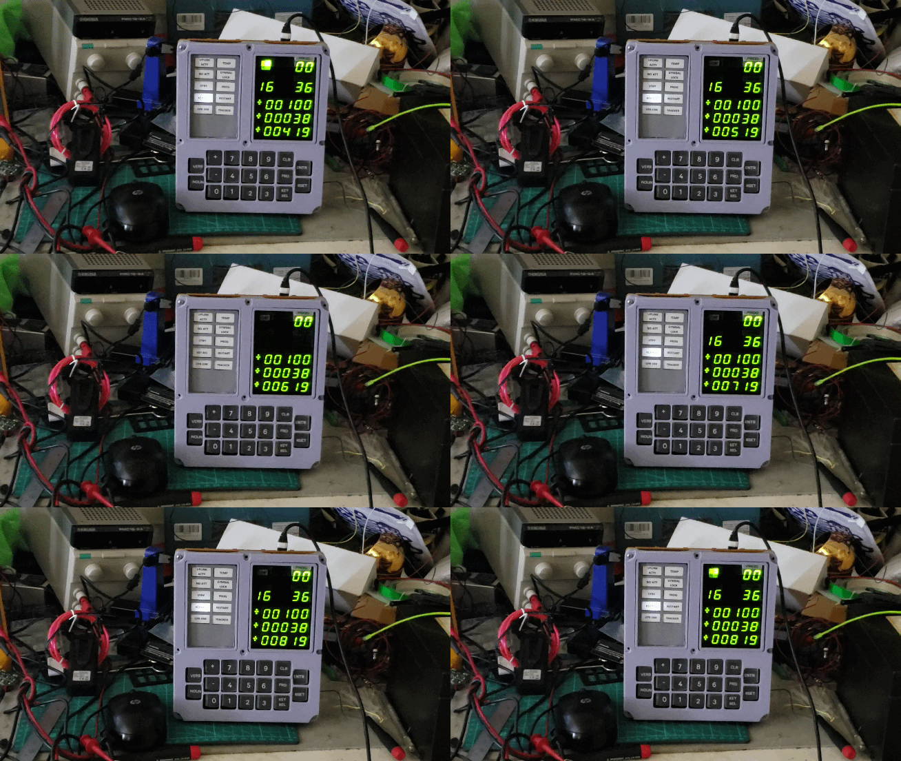 Running Apollo 11 CMD Module Software.
The circuit boards are mostly attached to a 1/8" plexiglas rear plate. The Teensey is mounted on female pin headers on the main display board. The Teensy actully slips thru a recetangular hole in the rear mounting plate.
The displays are multiplexed with the DP segments from the first two controlling the LED INDICATORS. Each lamp is controlled by the decimal point signals, which were not used in the original Apollo DSKY display. This turned out to be a good parts reduction as all the segments and Indicators can be controlle by only 3 LED controller chips.
Only the SEGMENT G and DP are used in the first display for each of the three registors to provide the segments for the SIGN digit. Since there is no known compatable SIGN LED Display - i put an array of SMT LEDs on the circuit board to represent this digit.
As you can see there is still some leakage between wells of the Indicator lamps but this is quite usable.
The lamps are separated with a matrix of opaque lattius. I made the prototype with popcicle
sticks, which turned out to be a litle short. I made a 3D printed chassis wich is way better!
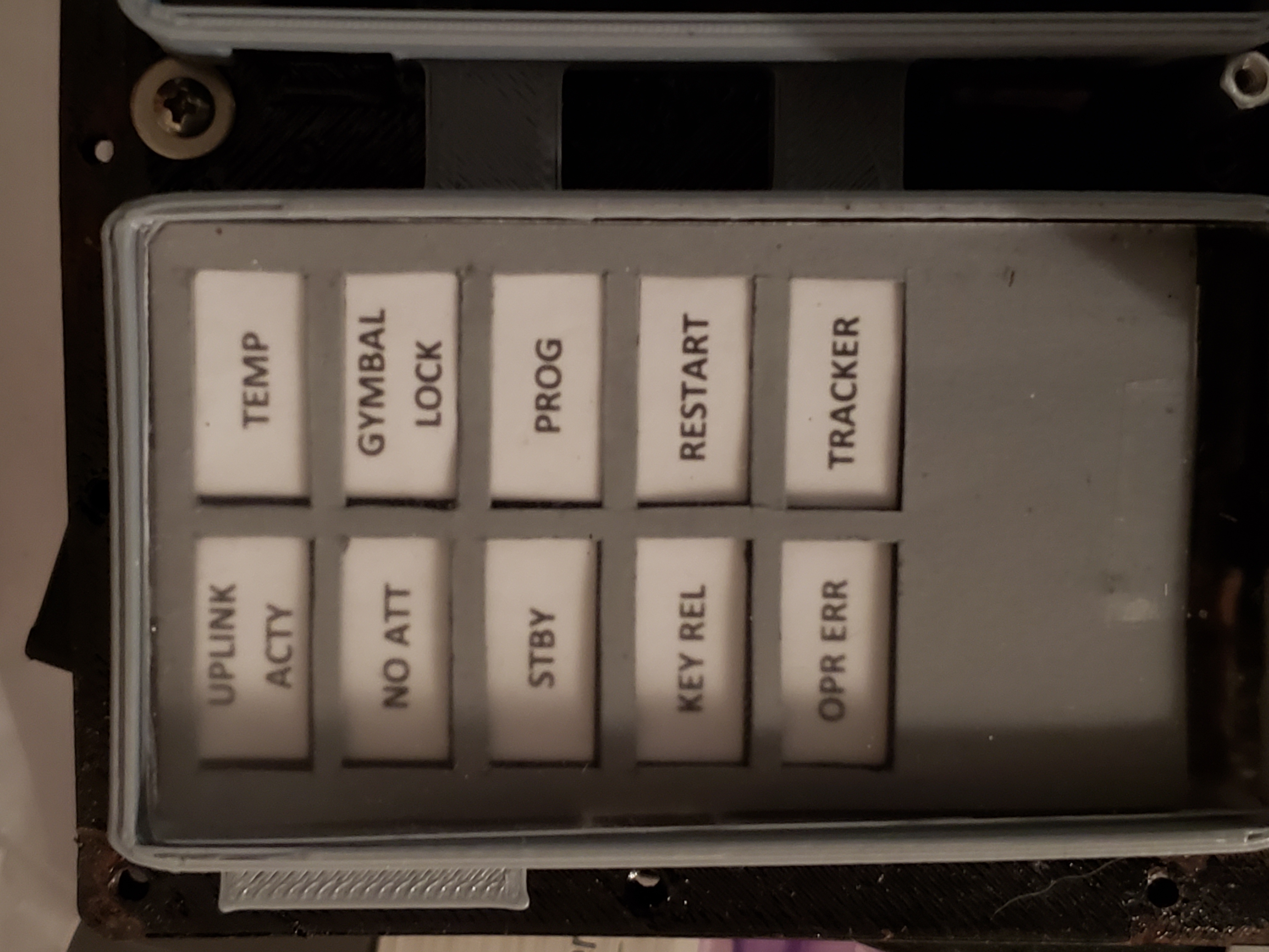 Indicator Display Mask
In all the dispalys work fine, but later I realized that if the displays were behind a card stock printout, behind some smoked grey plexiglas they look a lot like the original Apollo DSKY EL displays. But the LEDs were too far from the card stock to be seen. I then developed a pair of circuit boards, one to hold the LEDs and the other provides a light mask. This brings the sign digit near to the display. 67lb. White Cover Card stock (Staples Item 679482 to be exact). I
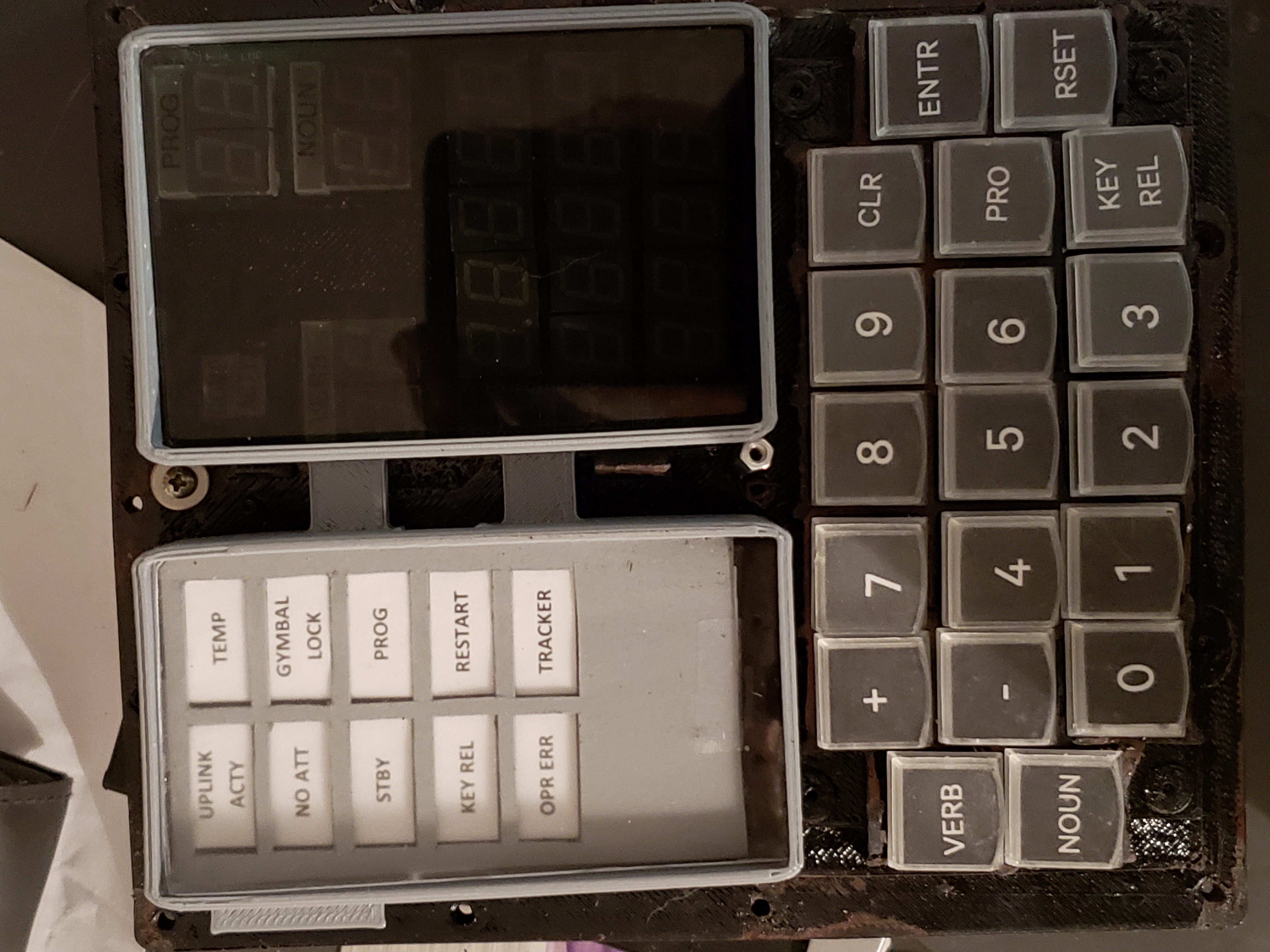
As you can see with the card stock the uDSKY is very simular to the DSKY as you cant really see the digits until they are illuminated. The only issue is the LED must be against the card stock for the effect to work. I did not have the sign LED digit boards working, and the prototype had the LEDs soldered to the main board, which is too far away to be seen thru the card stock.
No digits seen With power off
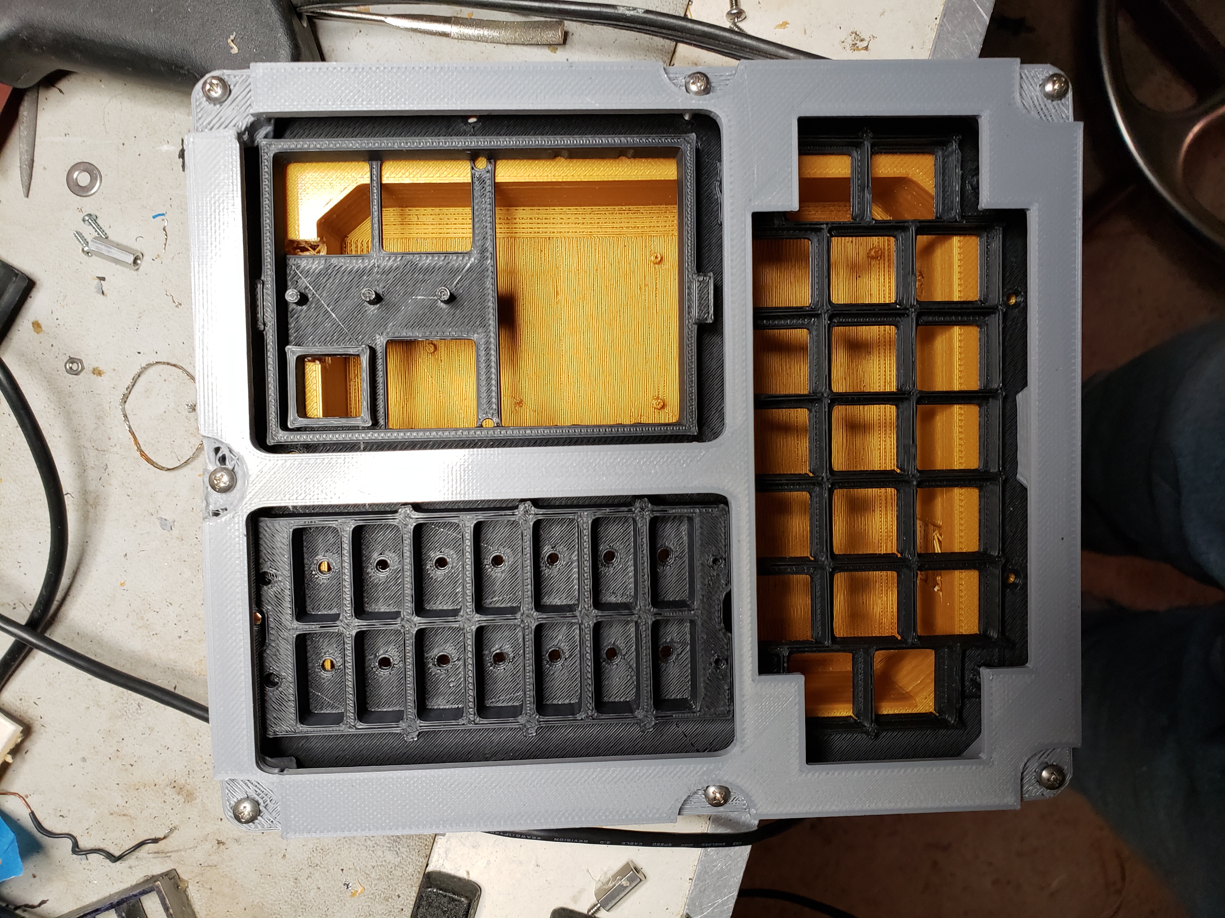
The 3D printed chasis is now on version 2. Here are a couple of shots of the first parts. It really started looking real, and as you can see from the .gif it is a lot better now than the original hand cut plexiglas.
The Keys are Cherry MX series. These have a real nice clicky feel and best of allthey can support custom keycaps and can be illuminated!
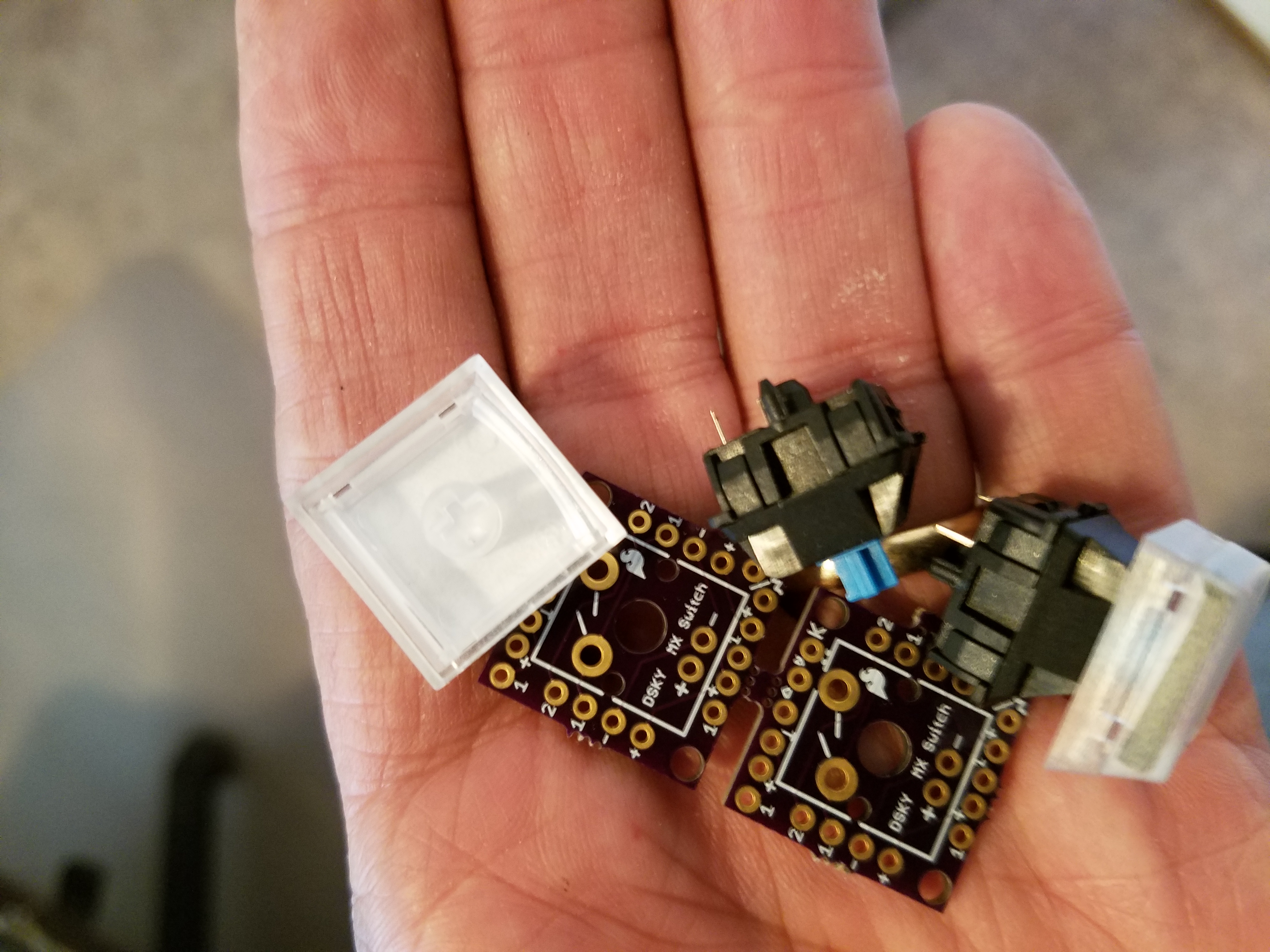 #The key caps are from: http:https://xkeys.com/accessories/Keycaps.php
They are not .75" x .75 which would be ideal but they have a little curve on the bottom
which makes the laser printed labels a little tricky to line up. But it works fairly well.
You will need 19 caps (4 orders will get you 20). I got both the clear and green. I thnk the black ones
owill be opaque so they can't be illuminated.
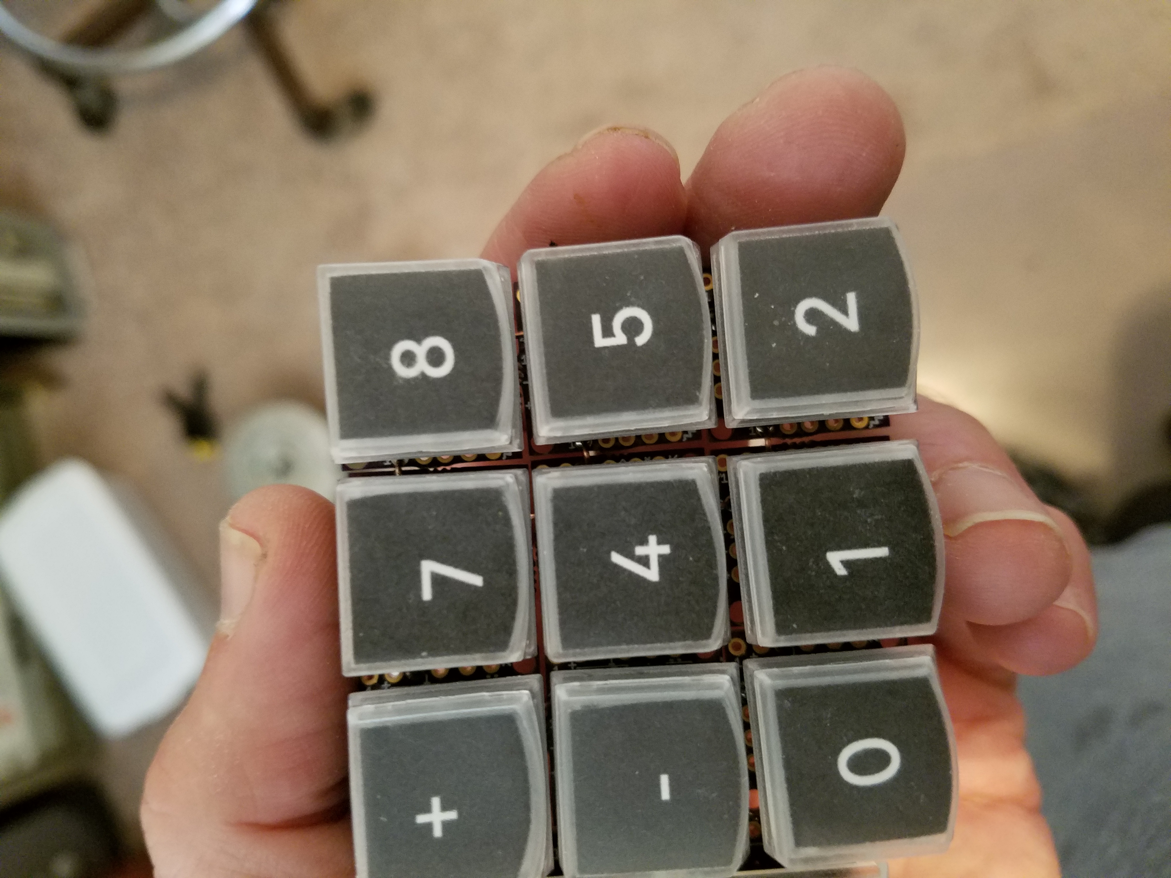 <Keys with relegendable keycaps for cherry mx switches
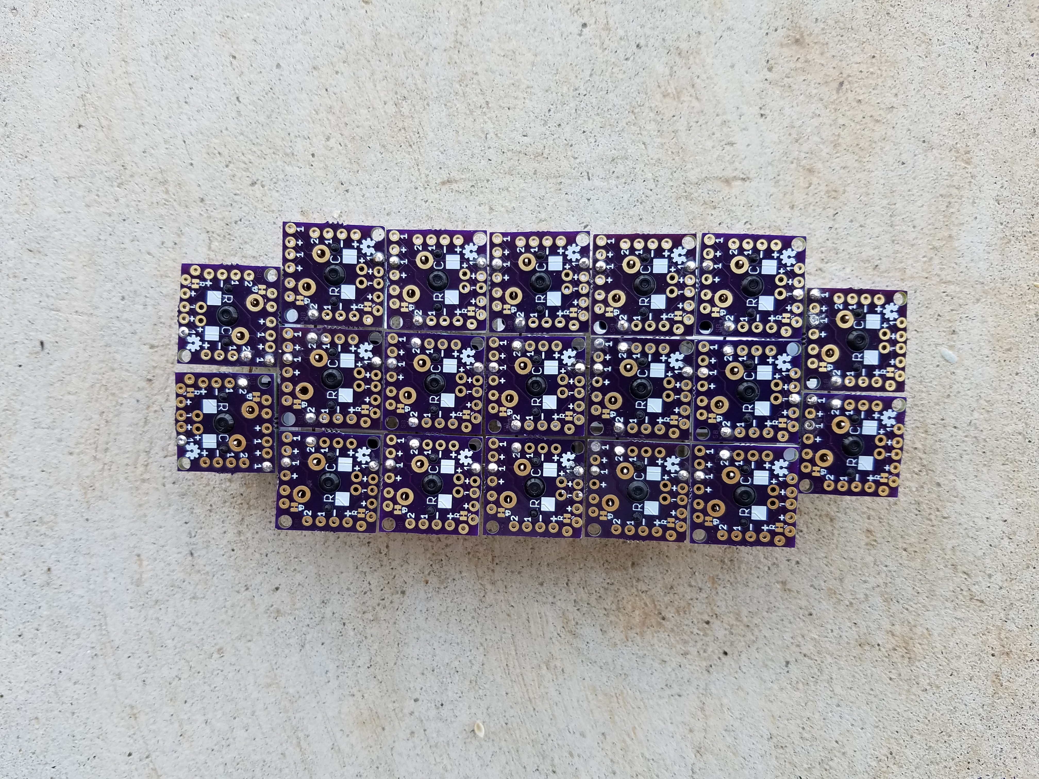
The Keys are simply mounted on an OSH Park Version of the SF MX breakout board. You can order them #or (BOB-13773) they are identical: https://www.sparkfun.com/products/13773 The next version I make may contain all 19 keys in one board. The 1 pins are all connected for ROWS and the 2 pins are for columns. Check out the Teensey code for the pattern and hookup. https://github.com/b-wave/uDSKY/tree/master/DSKY%20Arduino%20Files
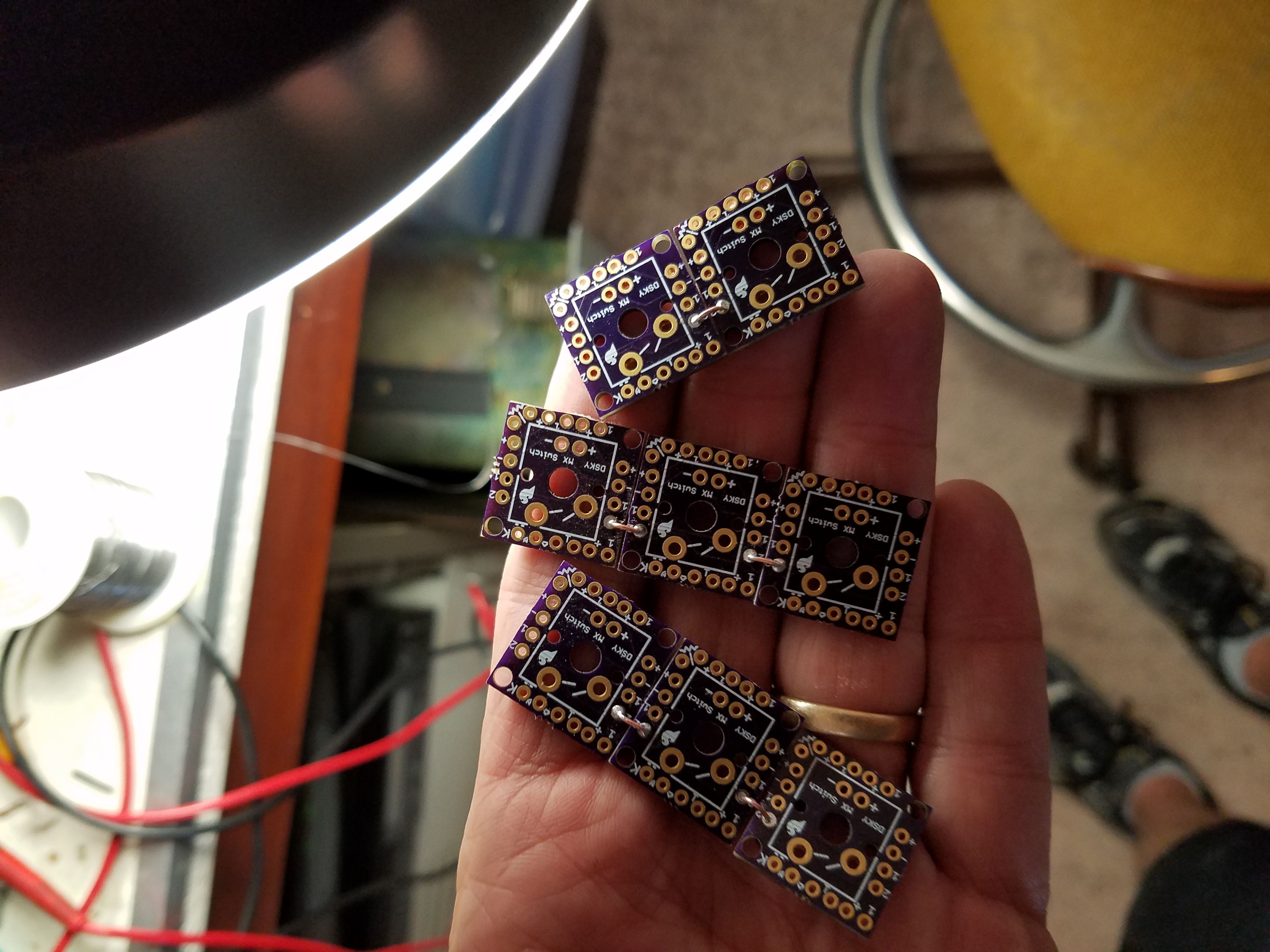 Breakout Column connections - using the 2 Pads.
The X/Y row - column pattern is fairly self-explanitory. The final assembly feels like holding some chain-mail armor. The only difficulties were to use small wire "U" shapes instead of straight from pin to pin. This makes the spacing of the keys line up to the holes on the base plate a little eaiser. The second is the two columns on the ends don't line up anyway on one side, it helps to flip those two end keys, the pads match and the keycap will still go on correctly. NOTE: see the flip keys on on the right hand side of bottom view:
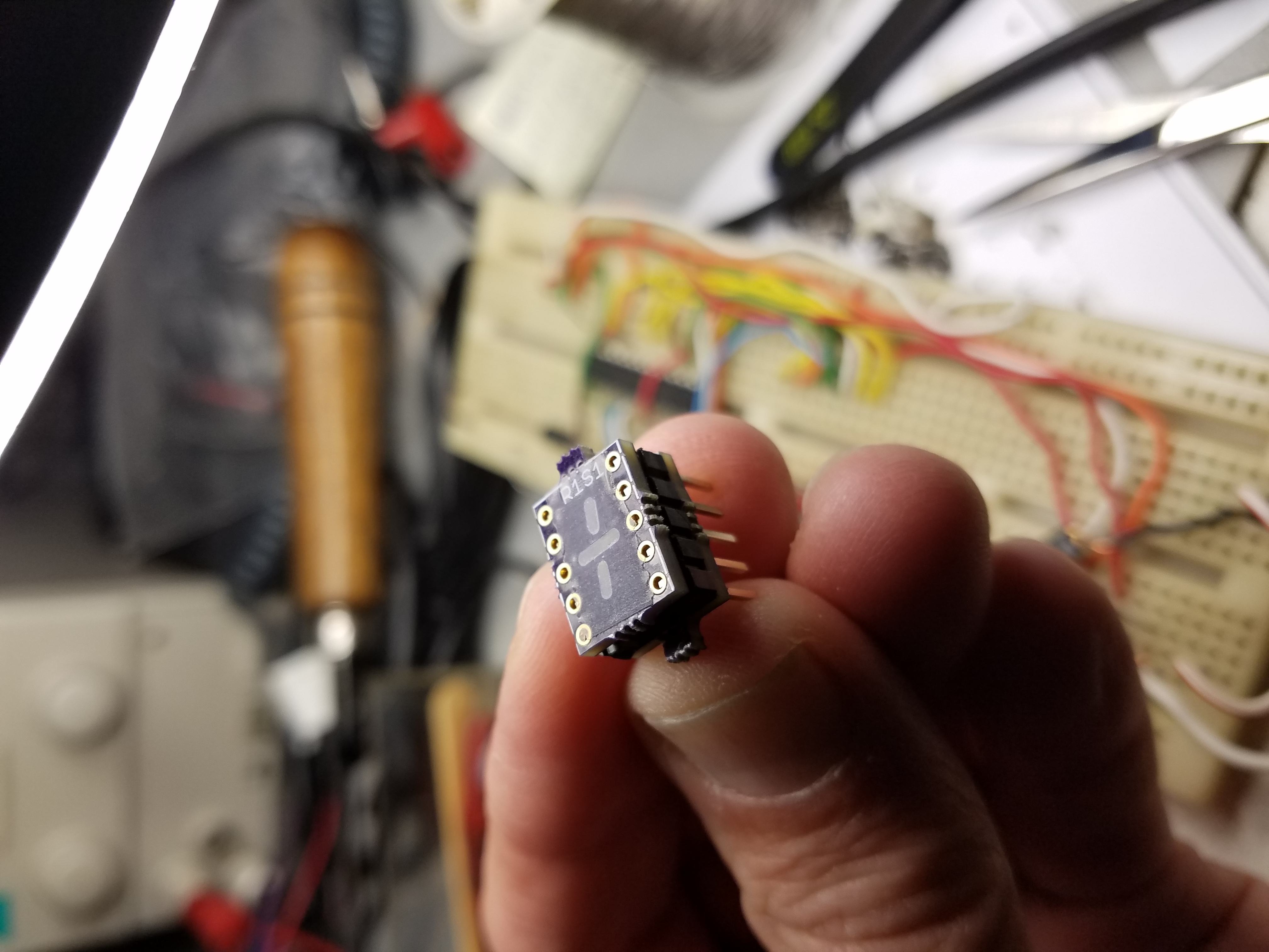
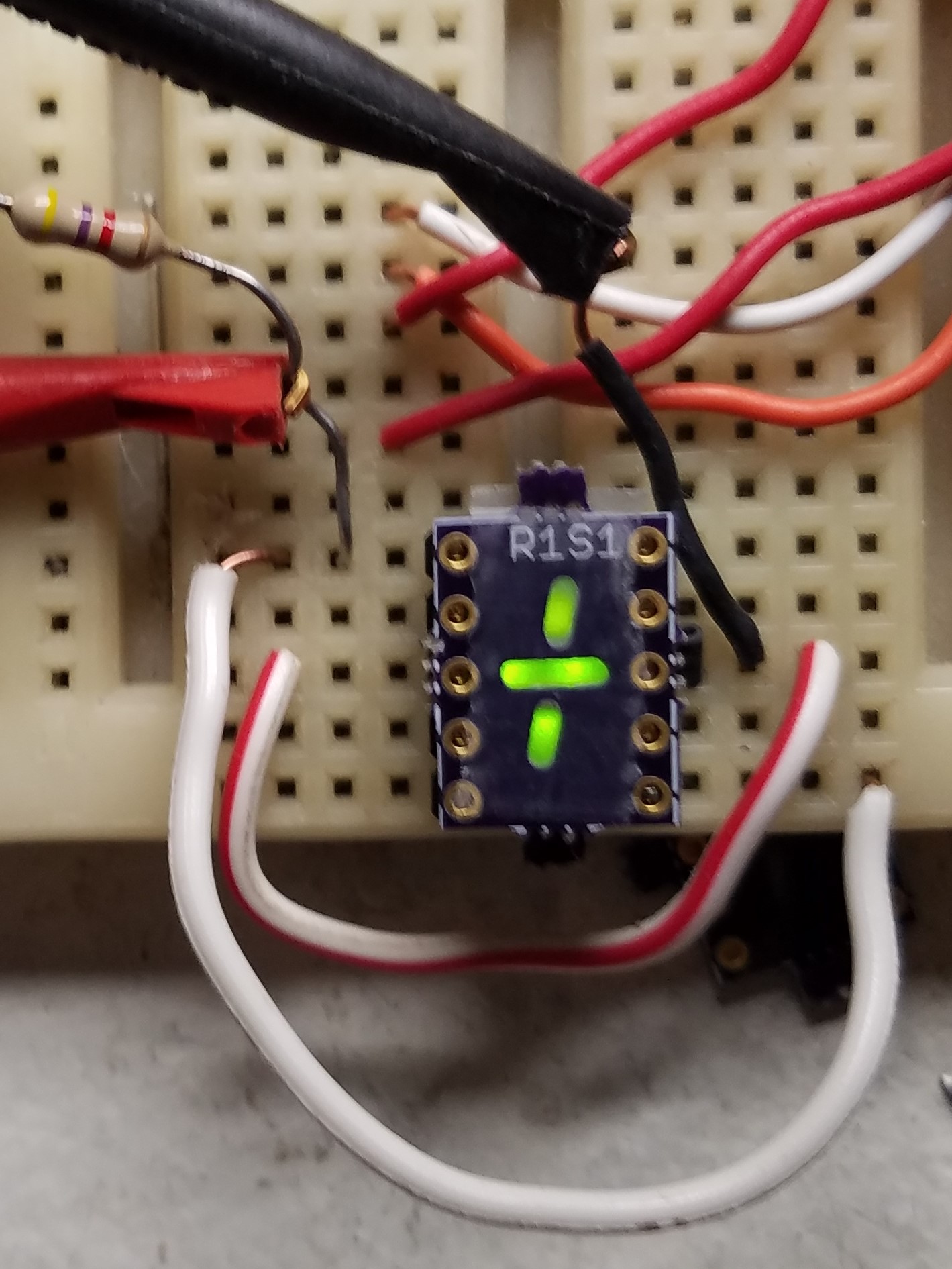
I developed a little circuit board set that will give a sign digit for each register. There are actully two other ways to get the sign digits. First, simply put in another 7-segment display. The G segment will be (-) and the DP will represent (+) ...blank is octal as usual Second, the board has pad for SMT LEDs that form the signs. G and DP illumiate the pairs of LEDs but this arrangement has the distance problem, but you can still use the mask board to make the displays look better.
This board will allow a pretty good substitute for the non-existent compatible LED sign digits for an Apollo DSKY display. You will also need the DS_MASK.brd https://oshpark.com/shared_projects/6qTKqnak for each display if you want the displays to be more segment-ty? There are also some additional masking and diffusing techniques that can be done to make these look really good.
This board set are intended to be used with a 0.39" 10-pin LED displays such as LTS-4301G that were used on the uDSKY display.
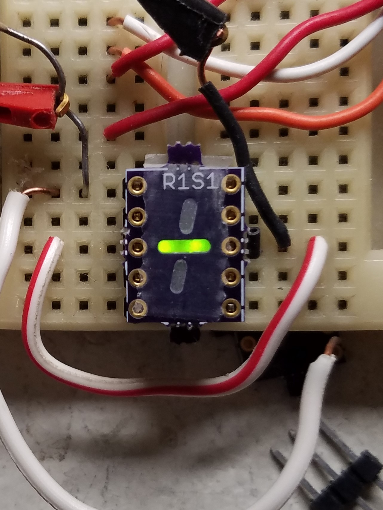
The minus (-) are controlled by the standard G - Segment Pin 1 with 2 LEDs in series. The (+) is a combination of the "g1" and "g2" Segs and the vertical segments (some times referred to as "h" and "J") which are connected to the "DP" pin 6. The Common pins are 8 and 3. Because both displays are two LEDs in series this should simplify non-MUX displays as well.
https://www.jameco.com/z/LTS-4301G-Lite-On-Electronics-Green-7-Segment-LED-Display_2227911.html
When selecting the SMT LEDs make sure you get them close to the brightness and color wavelength. For example , these LED displays have: 569 nm (green) with an avg. intensity = 2200 µCD @ If =10mA.
I can post some details on how to put these together. But basically, you need to diffuse the light or the viewing angle gets critical. A simple piece of scotch tape but hot melt glue may also work.
The parts placement is pretty simple, The anode of the first LED connects to the respective pin. The two LED's cathodes and anodes for each segment are connected together. The cathodes of the 2nd LEDs connect to the common pins. If you forget one LED or get one in backwards it's like Christmas tree light strings... no light for you!
A couple of baffles between the G and the vertical segments are also needed or when only (-) is displayed the other segments are still slightly visible. I used a couple scrap pieces of black wire insulation wedged between the segments to block this. The messy dabs of hot melt glue used to hold these in place are also visible.
Two 0.1" 5-pin headers to hold the two boards together. Mount the header on top of this board (long pins go thru the board) Then put the mask board on top of the header. The boards are separated by the plastic header. Push the pins flush to the top MSK_Brd Pins 1, 6, 8, and 3 now have to be soldered on the bottom of this board. You can solder the mask board's pins all in place if you want to - after you verify everything is working OK of course, there are no electrical connections to any other pads.
