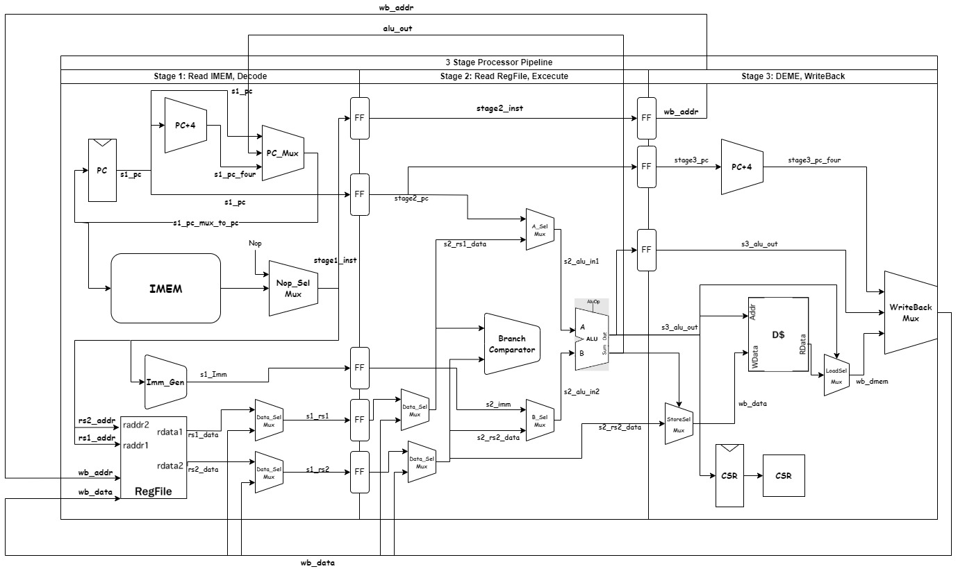
2024 Spring EECS151 asic project --> 3 stage RISCV processor.
Contributors(Project Team): Yu(Jaray) Li, Timonty Chu.
This is the final project of EECS151LA: ASIC Lab, where I participated as a visiting student in the spring semester of 2024. The goal is to design a 3-stage pipeline RISCV CPU processor. The project is divided into 4 checkpoints and a final checkoff. For details, please see this.
The ALU that we will implement in this lab is for a RISC-V instruction set architecture. Pay close attention to the design patterns and how the ALU is intended to function in the context of the RISC-V processor. In particular it is important to note the separation of the datapath and control used in this system which we will explore more here.
The specific instructions that your ALU must support are shown in the tables below. The branch condition should not be calculated in the ALU. Depending on your CPU implementation, your ALU may or may not need to do anything for branch, jump, load, and store instructions (i.e., it can just output 0).
One way of testing Verilog code is with testbench Verilog files. The outline of a test bench file has been provided for you in ALUTestbench.v. There are several key components to this file:
-
timescale 1ns / 1ps- This specifies, in order,the reference time unit and the precision. This example sets the unit delay in the simulation to 1ns (i.e.#1= 1ns) and the precision to 1ps (i.e. the finest delay you can set is#0.001= 1ps). -
The clock is generated by the code below. Since the ALU is only combinational logic, this is not necessary, but it will be a helpful reference once you have sequential elements.
- The
initialblock sets the clock to 0 at the beginning of the simulation. You should be sure to only change your stimulus when the clock is falling, since the data is captured on the rising edge. Otherwise, it will not only be difficult to debug your design, but it will also cause hold time violations when you run gate level simulation. - You must use an always block without a sensitivity list (the
@part of an always statement) to cause the clock to run automatically.
    parameter Halfcycle = 5; //half period is 5ns
    localparam Cycle = 2*Halfcycle;
    reg Clock;
    // Clock Signal generation:
    initial Clock = 0;
    always #(Halfcycle) Clock =  ̃Clock;
- The
-
task checkOutput; - this task contains Verilog code that you would otherwise have to copy paste many times. Note that it is not the same thing as a function (as Verilog also has functions). -
{$random} & 31'h7FFFFFFF- $random generates a pseudorandom 32-bit integer. A bitwise AND will mask the result for smaller bit widths.
An alternative way of testing is to use a test vector, which is a series of bit arrays that map to the inputs and outputs of your module. The inputs can be all applied at once if you are testing a combinational logic block or applied over time for a sequential logic block (e.g. an FSM).
You will write a Verilog testbench that takes the parts of the bit array that correspond to the inputs of the module, feeds those to the module, and compares the output of the module with the output bits of the bit array. The bit vector should be formatted as follows:
[106:100] = opcode
[99:97] = funct
[96] = add_rshift_type
[95:64] = A
[63:32] = B
[31:0] = REFout
Open up the skeleton provided to you in ALUTestVectorTestbench.v. You need to complete the module by making use of $readmemb to read in the test vector file (named testvectors.input), writing some assign statements to assign the parts of the test vectors to registers, and writing a for loop to iterate over the test vectors.
The syntax for a for loop can be found in ALUTestbench.v. $readmemb takes as its arguments a filename and a reg vector, e.g.:
reg [5:0] bar [0:20];
$readmemb("foo.input", bar);
You will also have to generate the test vectors used in your testbench. A test vector can either be specified in Verilog, or generated using a higher-level language like Python.
Test vectors are of the format specified above, with the 7 opcode bits occupying the left-most bits. We've also provided a test vector generator written in Python. However, the only R-type instruction it tests is add. Update tests/ALUTestGen.py to generate test vectors for all R-type instructions. You may find the comp function useful for performing signed comparisons.
