It is my project of Painting Robot done to pass at the end of semester of "Real-time Control Systems" class at University of Technology. It is only for simulation script for the FPGA configuration program by Xilinx, in this case xc3s200-5ft256.
Develop a controller for a given industrial process. Suggest a way of signaling and entering data from sensors. Draw a transition graph that describes the operation of the driver. Create files VHDL source and bindings file. Program the system and check the correct operation of the controller.
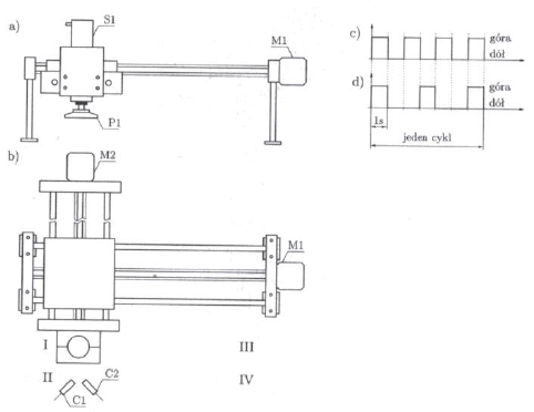
Fig. 1 Robot for painting objects: a) side view, b) top view, c) cycle of painting metal objects, d) cycle of painting non-metal objectsFigure 1 shows a diagram of a robot for painting objects. The robot's arms are moved by means of ball screws powered by M1 and M2 motors. At the end of the second the arm is mounted vertically with a single-acting pneumatic cylinder S1. At the end of the engine piston rod there is a suction cup S, used to catch painted objects. The robot is equipped with object presence sensors. Sensor C1 detects objects metal and non-metal, and the C2 sensor only metal objects.
In one process cycle, the robot occupies four positions:
- Rest position I;
- Place of collecting the item II;
- Place of painting III;
- Place of putting the item away IV.
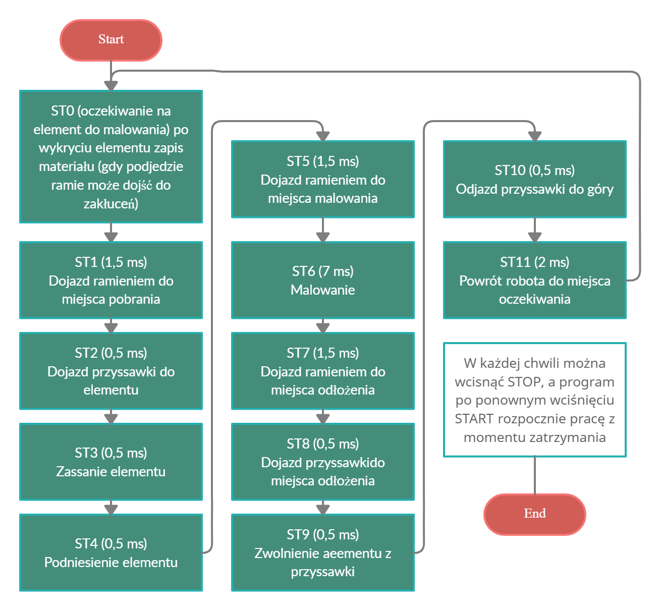
The work cycle of the robot begins after pressing the START button. The robot can be stopped at any time by pressing the STOP button. After pressing the START button, the robot starts working from the place where it was stopped. The work cycle is as follows:
- The robot waits in the rest position and for the appearance of an object;
- The item is put in place II. Sensors C1 and C2 detect the presence of an object, recognize the type of material (metal / non-metal) and give a signal to start the robot's movements;
- The robot arm moves to position II and the object is picked up by means of the P1 suction cup placed at the end of the S1 actuator piston rod;
- The item is transferred to painting site III, where the painting cycle is performed. Metal objects are painted in cycle c), while non-metal objects are painted in cycle d).
- The item is returned to its place. IV.
- The robot returns to the home position I. The cycle repeats from the beginning.
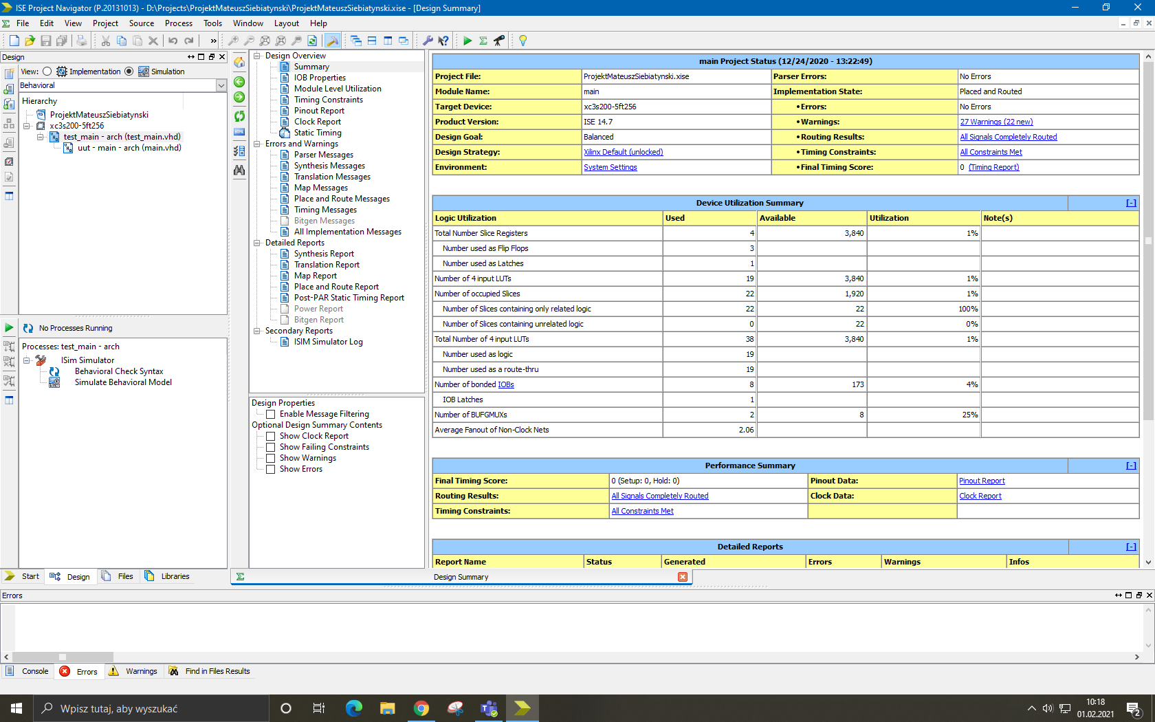
Fig. 2 Flowchart of a fully state machine based program Fig. 3 The window of the discussed project when starting the IDE
Name Description clk binary input for the clock START input signal from the START button STOP input signal from the STOP button C1 signal from the proximity sensor C2 signal from the metal sensor S1 signal that controls the single-acting pneumatic actuator P1 suction cup control signal M1 motor M1 control signal vector M2 motor M2 control signal vector
- clk - clock with a frequency of 100,000 [Hz] in the project,
- START - normally open monostable button (0 - rest, 1 - work activation driver),
- STOP - normally open monostable button (0 - rest, 1 - work stoppage driver),
- C1 - proximity sensor (0 - empty, 1 - object detection),
- C2 - metal sensor (0 - empty, 1 - metal detection),
- S1 - single-acting pneumatic cylinder (0 - retracted (upper position of the suction cup), 1 - extended (lower position of the suction cup))
- P1 - suction cup suction (0 - open, 1 - suction (grabbing an object))
- M1, M2 - 2-element vectors for motor control (1x - the engine is running, rotating, 0x - the engine is at rest, 11 - the rotation of the CCW motor (moving the sled away), 10 - the rotation of the CW motor (approximating the sledge))


