STM32 bootloader example that can jump to 2 apps.
This example contains a bootloader example, 2 app examples and a desktop app to flash binary files to a STM32.
Tutorial Video: https://youtu.be/S0s69xNE1dE
This bootloader example can jump to 2 different applications.
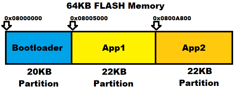
The FLASH memory (64KB) is splitted into multiple partitions.
The first partition (20KB) is for the bootloader.
The second partition is for the Application1 (22KB).
The third partion is for the Application2 (22KB).

To calculate offest in KB in binary, visit: https://www.gbmb.org/kb-to-bytes
Example:
20KB is 20480 Bytes.
Then convert that value (20480) to hexadecimal format (0x5000) in a calculator.
To find out what is your's MCU Page Size, read a Reference Manual: https://www.st.com/resource/en/reference_manual/cd00171190-stm32f101xx-stm32f102xx-stm32f103xx-stm32f105xx-and-stm32f107xx-advanced-arm-based-32-bit-mcus-stmicroelectronics.pdf
A bootloader is just an app that can jump to another application, erase the flash, or write a new data to the FLASH memory.
Applications are located in different sections of the FLASH memory, after the last bootloader sector ends.
Therefore applications need to have shifted the FLASH memory origin and offset in the vector table.
This bootloader listens to these commands via USB COM Port:
#define ERASE_FLASH_MEMORY "#$ERASE_MEM"
#define FLASHING_START "#$FLASH_START"
#define FLASHING_FINISH "#$FLASH_FINISH"
#define FLASHING_ABORT "#$FLASH_ABORT"
First use the "#$FLASH_START" command, to unlock the FLASH memory. This command also erases the FLASH memory if it was not erased.
Second when it receives 4 Bytes, which is a word, it will save it to the FLASH memory. So send your bin file 4 Bytes at once and wait for the answer "Flash: OK\n".
When you upload the whole "xyz.bin" file then you can send the "#$FLASH_FINISH" that will lock the FLASH memory.
Extra commands are "#$ERASE_MEM" that erases the FLASH memory and "#$FLASH_ABORT" that aborts the FLASH process, erases the FLASH memory and locks it.
Keep the flash origin, but change the size of the flash memory according to the bootloader size.
This bootloader has size under 20KB. Applications can start right from the next sector.
/* Memories definition */
MEMORY
{
  RAM    (xrw)    : ORIGIN = 0x20000000,   LENGTH = 20K
  FLASH    (rx)    : ORIGIN = 0x8000000,   LENGTH = 20K /*64K*/
}Here are just a few important fractions of the code:
#define APP1_START (0x08005000)			//Origin + Bootloader size (20kB)
#define APP2_START (0x0800A800)			//Origin + Bootloader size (20kB) + App1 Bank (22kB)
#define FLASH_BANK_SIZE (0X5800)		//22kB
#define FLASH_PAGE_SIZE_USER (0x400)	//1kB

typedef struct
{
    uint32_t		stack_addr;     // Stack Pointer
    application_t*	func_p;        // Program Counter
} JumpStruct;

void jumpToApp(const uint32_t address)
{
	const JumpStruct* vector_p = (JumpStruct*)address;

	deinitEverything();

	/* let's do The Jump! */
    /* Jump, used asm to avoid stack optimization */
    asm("msr msp, %0; bx %1;" : : "r"(vector_p->stack_addr), "r"(vector_p->func_p));
}

void deinitEverything()
{
	//-- reset peripherals to guarantee flawless start of user application
	HAL_GPIO_DeInit(LED_GPIO_Port, LED_Pin);
	HAL_GPIO_DeInit(USB_ENABLE_GPIO_Port, USB_ENABLE_Pin);
	USBD_DeInit(&hUsbDeviceFS);
	  __HAL_RCC_GPIOC_CLK_DISABLE();
	  __HAL_RCC_GPIOD_CLK_DISABLE();
	  __HAL_RCC_GPIOB_CLK_DISABLE();
	  __HAL_RCC_GPIOA_CLK_DISABLE();
	HAL_RCC_DeInit();
	HAL_DeInit();
	SysTick->CTRL = 0;
	SysTick->LOAD = 0;
	SysTick->VAL = 0;
}
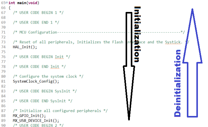
In order to safely deinitialize a MCU it is good to check in what order it was initialized, and deinitialize it in the opposite order.

Bootloader (USB COM Port Communication Interface) - usbd_cdc_if.c
static int8_t CDC_Receive_FS(uint8_t* Buf, uint32_t *Len)
{
  /* USER CODE BEGIN 6 */
  USBD_CDC_SetRxBuffer(&hUsbDeviceFS, &Buf[0]);
  USBD_CDC_ReceivePacket(&hUsbDeviceFS);
  //my code begin
	HAL_GPIO_WritePin(LED_GPIO_Port, LED_Pin, GPIO_PIN_RESET);//LED ON
	uint16_t length = (uint16_t) *Len;
	if(length == 4 && flashStatus == Unlocked)
	{
		uint32_t dataToFlash = (Buf[3]<<24) +
							  (Buf[2]<<16) +
							  (Buf[1]<<8) +
							  Buf[0];//32bit Word contains 4 Bytes
		flashWord(dataToFlash);
	}else
	{
		messageHandler(Buf);
	}
	HAL_GPIO_WritePin(LED_GPIO_Port, LED_Pin, GPIO_PIN_SET);//LED OFF
  //my code end
  return (USBD_OK);
  /* USER CODE END 6 */
}
There is a simple message handler in "bootloader.c" that handles received commands:
void messageHandler(uint8_t* Buf)
{
	if(string_compare((char*)Buf, ERASE_FLASH_MEMORY, strlen(ERASE_FLASH_MEMORY))
			&& flashStatus != Unlocked)
	{
		eraseMemory();
		CDC_Transmit_FS((uint8_t*)&"Flash: Erased!\n", strlen("Flash: Erased!\n"));
	}else if(string_compare((char*)Buf, FLASHING_START, strlen(FLASHING_START)))
	{
		unlockFlashAndEraseMemory();
		CDC_Transmit_FS((uint8_t*)&"Flash: Unlocked!\n", strlen("Flash: Unlocked!\n"));
	}else if(string_compare((char*)Buf, FLASHING_FINISH, strlen(FLASHING_FINISH))
			  && flashStatus == Unlocked)
	{
		lockFlash();
		CDC_Transmit_FS((uint8_t*)&"Flash: Success!\n", strlen("Flash: Success!\n"));
	}else if(string_compare((char*)Buf, FLASHING_ABORT, strlen(FLASHING_ABORT))
			  && flashStatus == Unlocked)
	{
		lockFlash();
		eraseMemory();
		CDC_Transmit_FS((uint8_t*)&"Flash: Aborted!\n", strlen("Flash: Aborted!\n"));
	}else
	{
		CDC_Transmit_FS((uint8_t*)&"Error: Incorrect step or unknown command!\n",
			  strlen("Error: Incorrect step or unknown command!\n"));
	}
}App1 (Application 1) - FLASH.ld
/* Memories definition */
MEMORY
{
  RAM    (xrw)    : ORIGIN = 0x20000000,   LENGTH = 20K
  FLASH    (rx)    : ORIGIN = 0x8005000,   LENGTH = 22K /*64K*/
}
App2 (Application 2) - FLASH.ld
/* Memories definition */
MEMORY
{
  RAM    (xrw)    : ORIGIN = 0x20000000,   LENGTH = 20K
  FLASH    (rx)    : ORIGIN = 0x800A800,   LENGTH = 22K /*64K*/
}App1 (Application 1) - Code Summary
  	  /*
  	   * App1
  	   * change the flash size and flash origin in FLASH.ld file like:
  	   * FLASH    (rx)    : ORIGIN = 0x8005000,   LENGTH = 22K //64K
  	   *
  	   * in system_stm32f1xx.c change VECT_TAB_OFFSET to your new value like 0x00005000U
  	   * #define USER_VECT_TAB_ADDRESS //First uncomment this in system_stm32f1xx.c
  	   * #define VECT_TAB_OFFSET         0x00005000U
  	   */
App1 (Application 1) - system_stm32f1xx.c
/* Note: Following vector table addresses must be defined in line with linker
         configuration. */
/*!< Uncomment the following line if you need to relocate the vector table
     anywhere in Flash or Sram, else the vector table is kept at the automatic
     remap of boot address selected */
 #define USER_VECT_TAB_ADDRESS //Uncommented this

#if defined(USER_VECT_TAB_ADDRESS)
/*!< Uncomment the following line if you need to relocate your vector Table
     in Sram else user remap will be done in Flash. */
/* #define VECT_TAB_SRAM */
#if defined(VECT_TAB_SRAM)
#define VECT_TAB_BASE_ADDRESS   SRAM_BASE       /*!< Vector Table base address field.
                                                     This value must be a multiple of 0x200. */
#define VECT_TAB_OFFSET         0x00000000U     /*!< Vector Table base offset field.
                                                     This value must be a multiple of 0x200. */
#else
#define VECT_TAB_BASE_ADDRESS   FLASH_BASE      /*!< Vector Table base address field.
                                                     This value must be a multiple of 0x200. */
#define VECT_TAB_OFFSET         0x00005000U     /*!< Vector Table base offset field.
                                                     This value must be a multiple of 0x200. */
#endif /* VECT_TAB_SRAM */
#endif /* USER_VECT_TAB_ADDRESS */
App2 (Application 2) - Code Summary
	  /*
	   * App2
	   * change the flash size and flash origin in FLASH.ld file like:
	   * FLASH    (rx)    : ORIGIN = 0x800A800,   LENGTH = 22K //64K
	   *
	   * in system_stm32f1xx.c change VECT_TAB_OFFSET to your new value like 0x0000A800U
	   * #define USER_VECT_TAB_ADDRESS //First uncomment this in system_stm32f1xx.c
	   * #define VECT_TAB_OFFSET         0x0000A800U
	   */
App2 (Application 2) - system_stm32f1xx.c
/* Note: Following vector table addresses must be defined in line with linker
         configuration. */
/*!< Uncomment the following line if you need to relocate the vector table
     anywhere in Flash or Sram, else the vector table is kept at the automatic
     remap of boot address selected */
 #define USER_VECT_TAB_ADDRESS //Uncommented this

#if defined(USER_VECT_TAB_ADDRESS)
/*!< Uncomment the following line if you need to relocate your vector Table
     in Sram else user remap will be done in Flash. */
/* #define VECT_TAB_SRAM */
#if defined(VECT_TAB_SRAM)
#define VECT_TAB_BASE_ADDRESS   SRAM_BASE       /*!< Vector Table base address field.
                                                     This value must be a multiple of 0x200. */
#define VECT_TAB_OFFSET         0x00000000U     /*!< Vector Table base offset field.
                                                     This value must be a multiple of 0x200. */
#else
#define VECT_TAB_BASE_ADDRESS   FLASH_BASE      /*!< Vector Table base address field.
                                                     This value must be a multiple of 0x200. */
#define VECT_TAB_OFFSET         0x0000A800U     /*!< Vector Table base offset field.
                                                     This value must be a multiple of 0x200. */
#endif /* VECT_TAB_SRAM */
#endif /* USER_VECT_TAB_ADDRESS */
For more details just explore the project example.
This Java application uses a JRE to run.
It can run on any OS (Windows, Linux or Mac).
Executable JAR file can be downloaded here:
https://github.com/viktorvano/STM32-Bootloader/blob/master/STM32Flasher/out/artifacts/STM32Flasher_jar/STM32Flasher.jar?raw=true
If you have flashed the bootloader into the STM32, you can use this STM32 Flasher to flash those app examples, or your own apps.
1.) Set the BOOT1 pin to logical 1 state on the STM32.
2.) Use the switch (B11 pin) on the STM32 board to select the app you want to flash or erase.
3.) Connect the STM32 board to a computer.
4.) Launch the "STM32Flasher.jar".
5.) Select the "Bootloader ComPort" and connect. Now you have the option to erase your current selected app from the STM32.
6.) Click the "File" button to choose your binary file. Your binary app has to match with step 2 (for example App1.bin for the App1 partition), otherwise any iterrupt will not work and the STM32 app will be stuck when it tries to run (the vector table will not match).
7.) Click the "Flash" button. It should be flashed within a few seconds.
8.) Click "Disconnect" and close STM32 Flasher app.
9.) Set the BOOT1 pin to logical 0 state on the STM32 and reset the STM32 board. Now your app will run.


