-
Notifications
You must be signed in to change notification settings - Fork 0
🛠️ Build tutorial
Antoine Chatelain edited this page Feb 8, 2023
·
4 revisions
In this section you will find all the necessary information to build your very own Adiclock!
+----+---------------+----------+----------------------------------------------------------+
| n° |     Name      | Quantity |                           Note                           |
+----+---------------+----------+----------------------------------------------------------+
|  1 | SG90          |       35 | Servo motor                                              |
|  2 | Segment       |       35 | 3D print segment.stl                                     |
|  3 | Holder        |       35 | 3D print holder.slt                                      |
|  4 | Base board    |        5 | Size 390x200*10mm place holes according to baseboard.dxf |
|  5 | PCA9685       |        3 | See code to place solder bridge                          |
|  6 | M4X20         |       70 | Used to secure the holder to the base board              |
|  7 | M4 nuts       |       70 | Used to secure the holder to the base board              |
|  8 | M3X8          |       40 | Used to secure the stud to the base board                |
|  9 | angle bracket |       20 | Used to secure the stud to the base board                |
| 10 | 5V 20W PSU    |        1 | Used to power the clock                                  |
| 11 | ESP 32        |        1 | Controls everything                                      |
+----+---------------+----------+----------------------------------------------------------+
- Small flat head screwdriver
- Philips head screwdrivers
- Soldering iron + soldering essentials
- Black paint or black spray paint can
- Yellow vinyl
- Utility knife
- Wire cutters
- Wire Stripers
- Wood saw
- Drill with small wood drill bit
- 3D printer
- Laser cutter or CNC machine
- Automated vinyl cutter / sticker maker
1. 🔧 Print or build the segments and holders according to segment.slt or segment.pdf paint them if necessary
2. 🔩 Assemble the segments and holders according to Segment assembly part list.pdf
3. 🪚 Cut 5 baseboard according to baseboard.pdf.
Use a CNC machine or laser cutter to make life easier
Take time to pass the wires before bolting
If you want to reuse our code be sure to report to AdiClock part list.pdf.
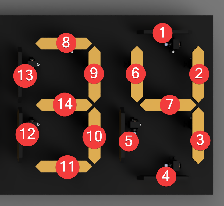
To see were the servos are connected use the picture below

Apply this principle to the first and last too modules. Wire the middle one last and use the same numbering scheme from 1 to 7