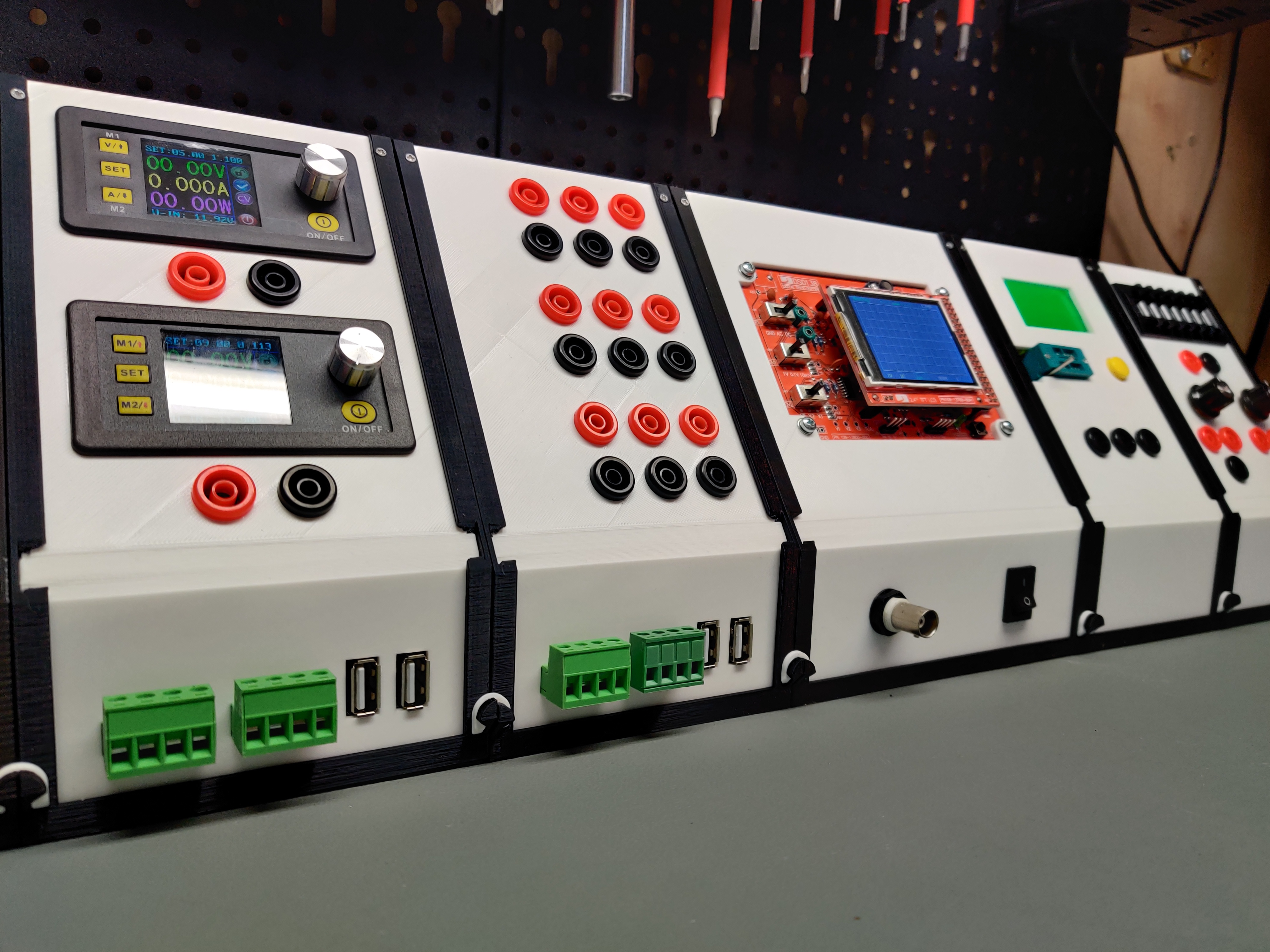
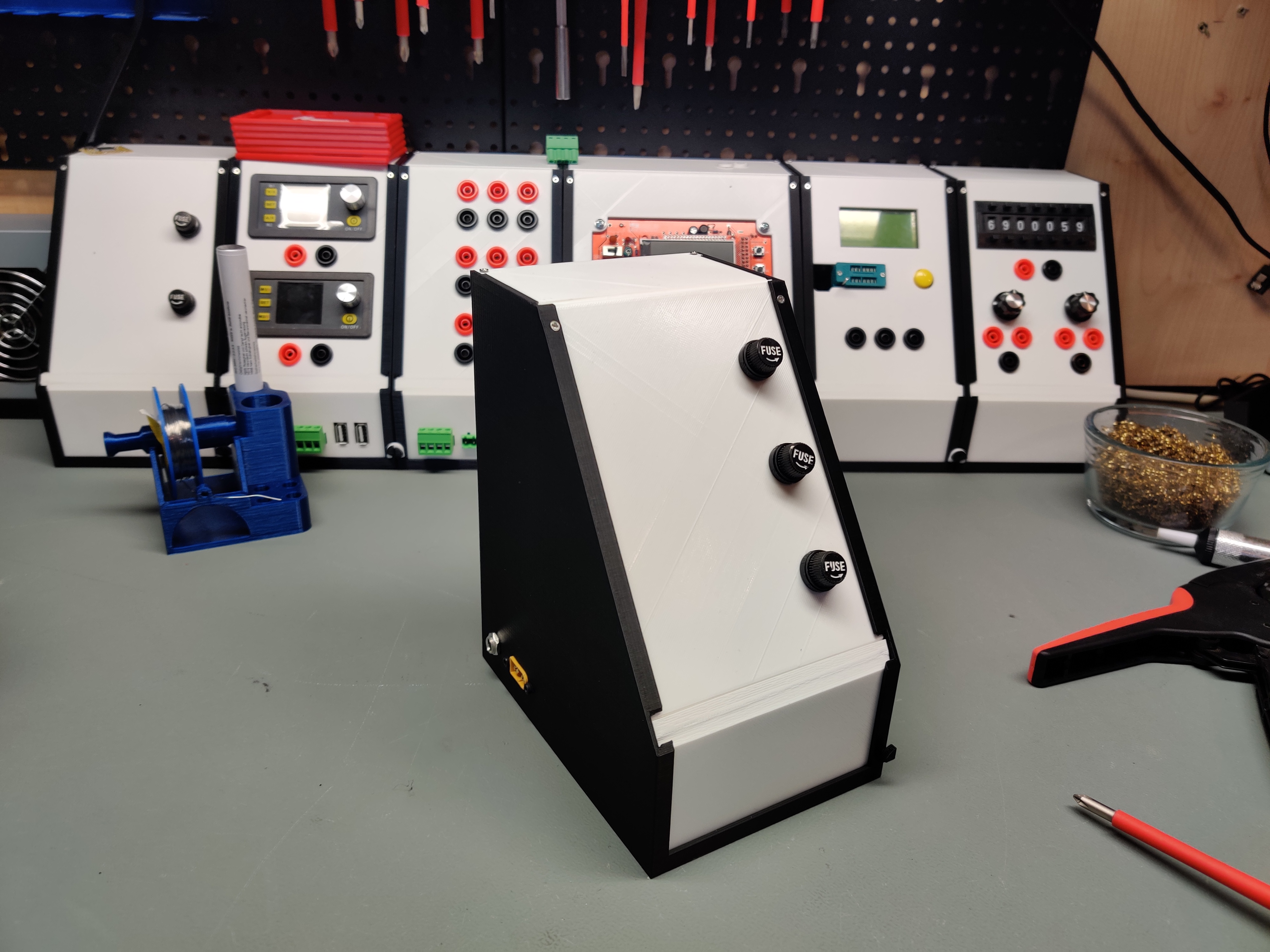
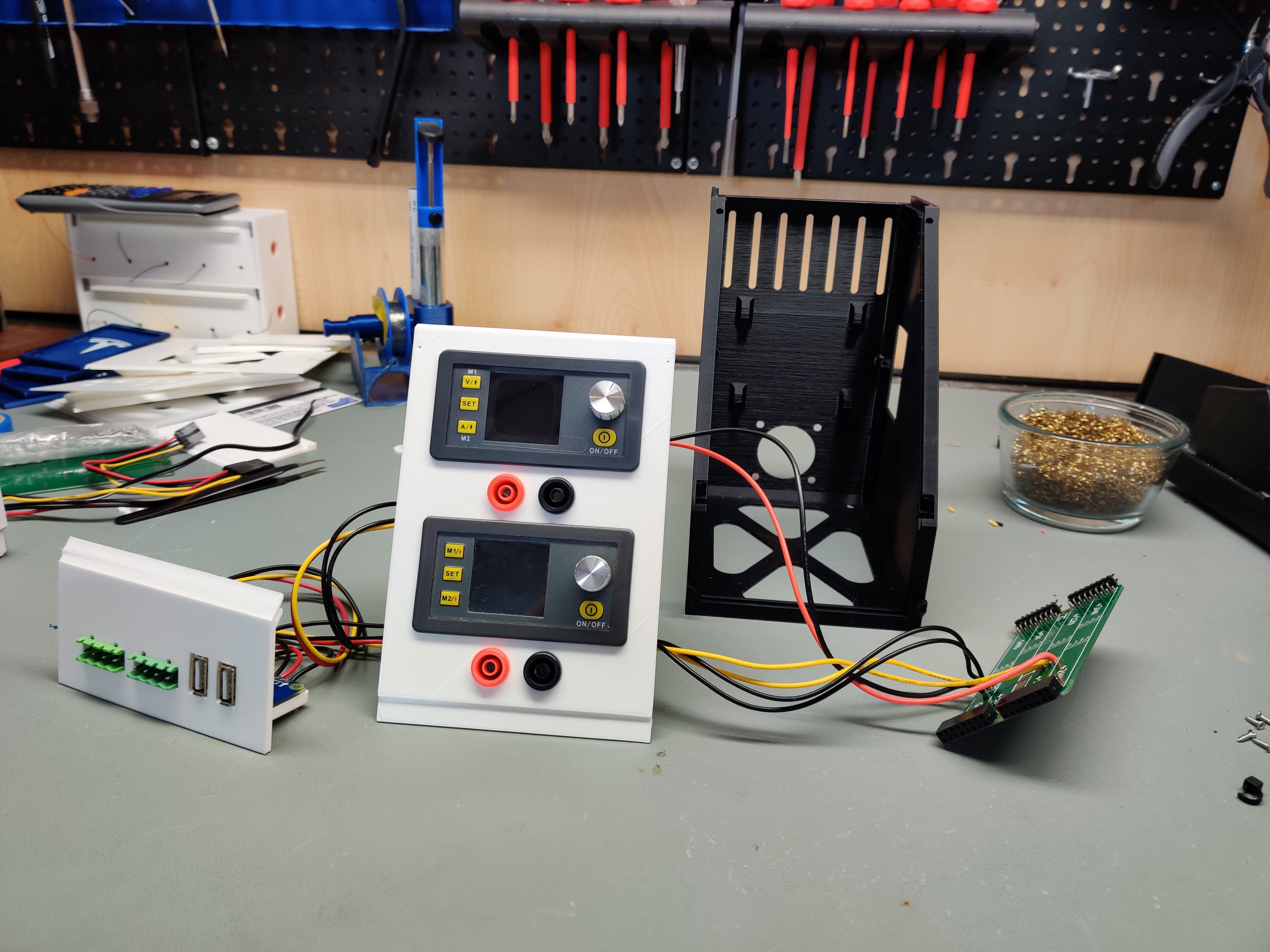
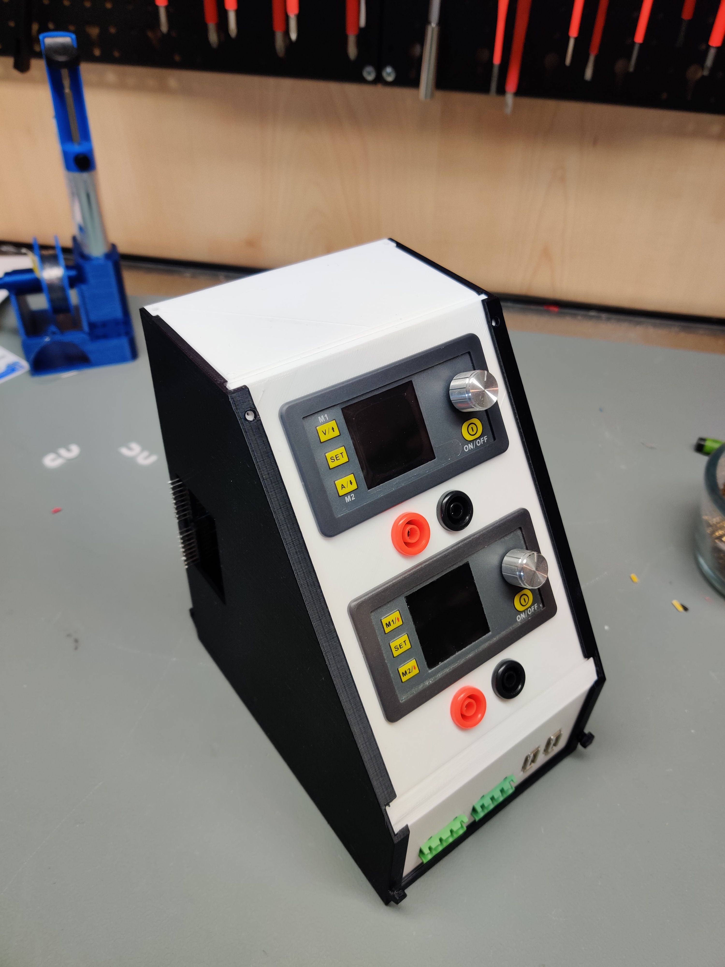
This is a low cost, modular elctronics lab system for hobbyists. The customizable modules include fixed and variable power supplies, measurement tools, component testers and much more. Everything in here is done with open source software, including FreeCAD for all the 3d printable files and KiCAD for the PCBs. I have made a set of modules already and am in the process of creating many more. Raw PCB project files, Gerbers and FreeCAD projects are all uploaded here for your customizing needs, while the finished modules are uploaded to Thingiverse. Please be sure to upload any remix you do as it might be useful for others and especially myself!
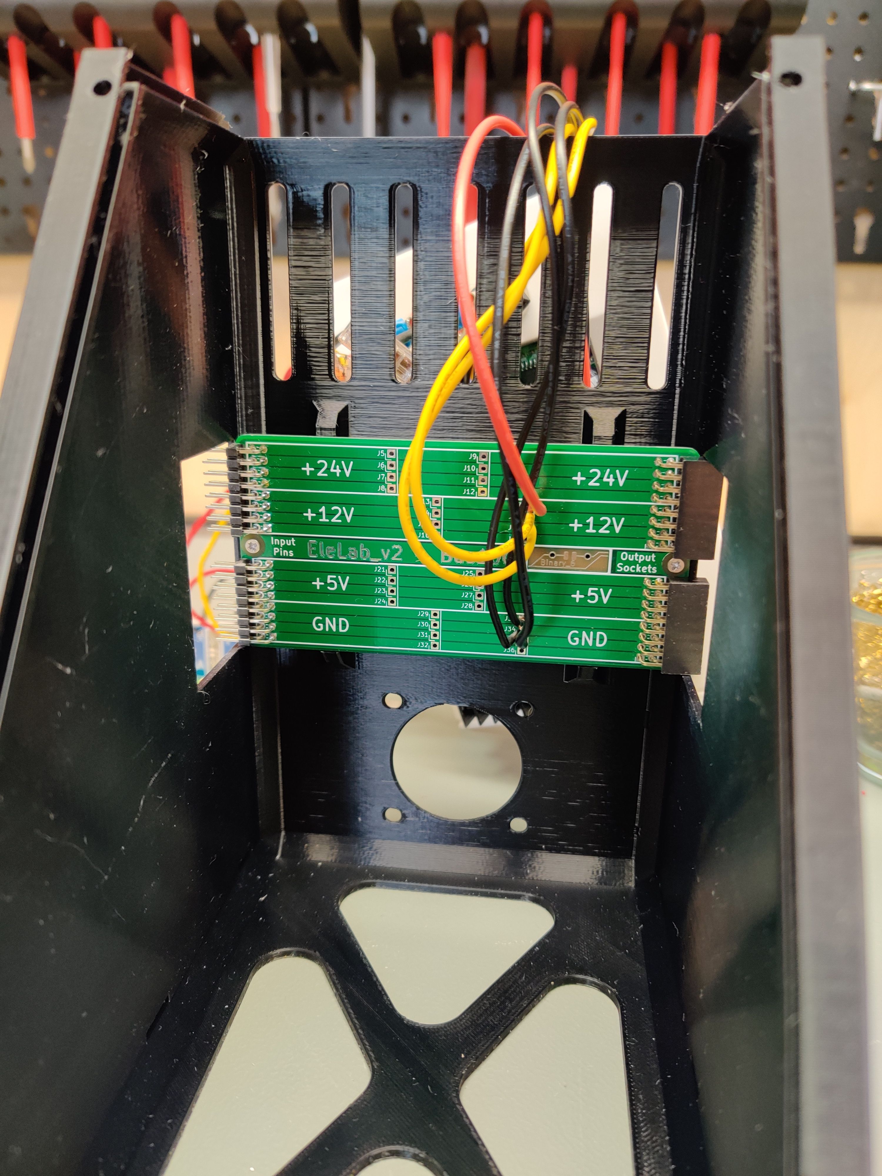
The system features a set of backpanel bus PCBs as well as panel breakout PCBs. While the backpanel bus is not neccesary, it keeps the system modular, hot swappable and tidy. You can have the gerbers manufactured for cheap at your favorite chinese PCB house or just shoot me a message. I might have spares.
Finished modules for printing yourself for any module can be found here in my Thingiverse collection. For most of the modules a printbed of 160x160mm and 175mm of height is sufficient, but the ATX and SFX module require print bed sizes of up to 250mm width (Prusa MK2 and up dimensions). I printed all of the modules in PLA and just to speed things up i used a 0.6mm nozzle but that is not required at all.
If you like my work please consider supporting my caffeine addiction!
- Signal Tracer (Display and audio)
- Function Generator
- Epaper + ESP8266
- Solder sponge / wire holder + TS100 output
The system consists of 3 basic sizes of modules, 100mm, 150mm and 200mm. For the 100mm and the 150mm frame there is a backpanel bus that interconnects the modules together for power delivery. The 200mm frame uses two of the 100mm PCBs.
For the modules we usually use one of the 3 base sizes and punch holes in the upper and/or lower front panel to suit our mounting needs. This can be done in FreeCAD by modifying the BaseXXX file or a finished module that best fits your new module. Alternatively you can also just edit the .stl files in the editor of your choice.
The backpanel bus is equipped to transfer 24 V, 12 V and 5 V (and GND, duh), which we feed into the system by one of the "Supply" modules. At the moment i made an SFX-PSU supply module (supplying 12 V and 5 V) and one with a 5.5mm barrel jack and XT60 jack (Using 24 V supplies and step-down converters for 12 V and 5 V). Both of these supply modules feature the PowerFeed PCB to feed into the backpanel bus. Because 24 V is rarely needed for most of the modules, the easiest and safest way to use this system is the SFX module, which just plugs into the PowerFeed PCB.
Obviously you can just run wires between the modules and omit the backpanel bus, but it will probably make me a little sad.
If you are using the bus, individual modules just plug into each other to form a single unit.
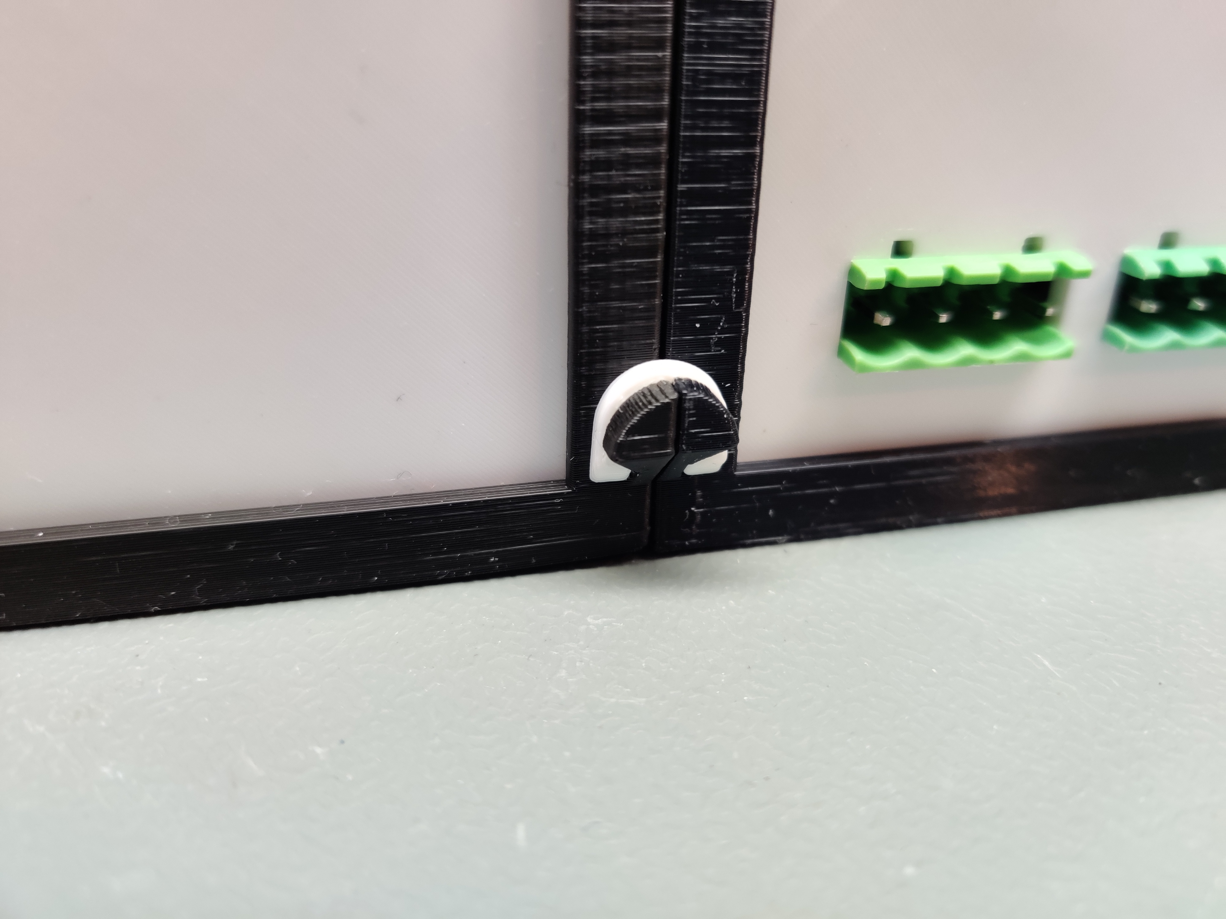
With 2 little printed clips you can secure the modules together so they don't seperate during the occasional earthquake or lab-ragequit.
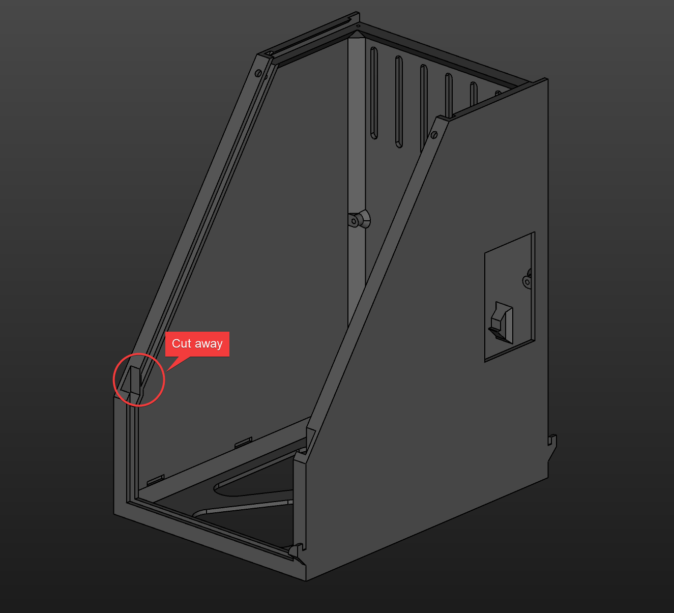
Almost none of the 3d printable pieces require supports. The frame of each module has integrated supports at one position, that you will need to cut away after printing:
All of the PCBs can be cheaply manufactured in China (trust me, it's easier and cheaper than you think) or sometimes i even have spares left, if you shoot me a message.
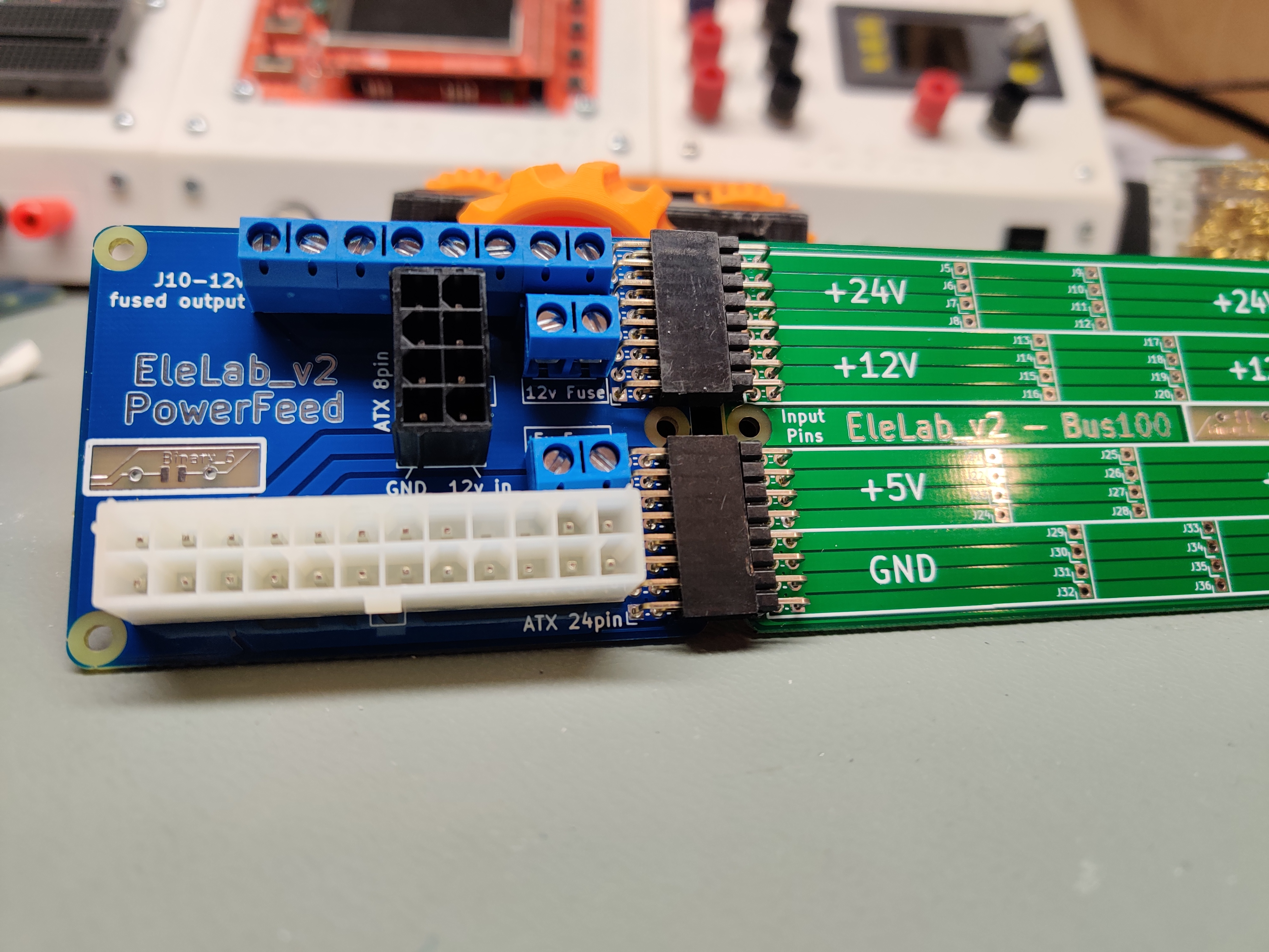
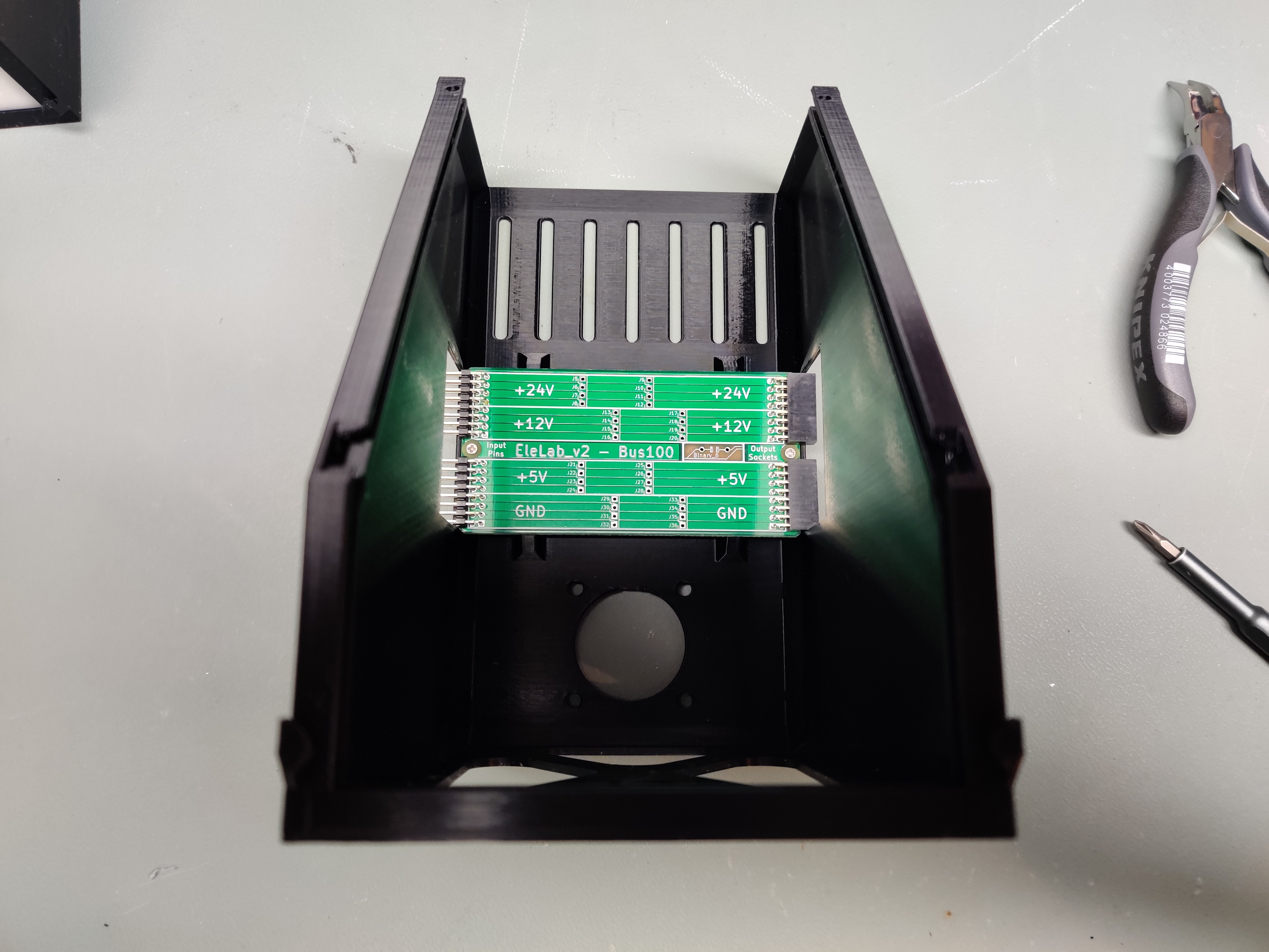
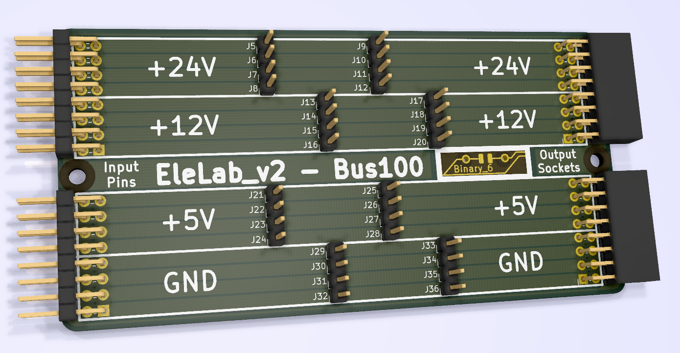
This is the basic backpanel bus to link individual modules together. Though optional, it greatly enhances your experience in building this system.
Parts:
- 2pcs 2.54mm Pinheader right angle 2x8 female
- 2pcs 2.54mm Pinheader right angle 2x8 male
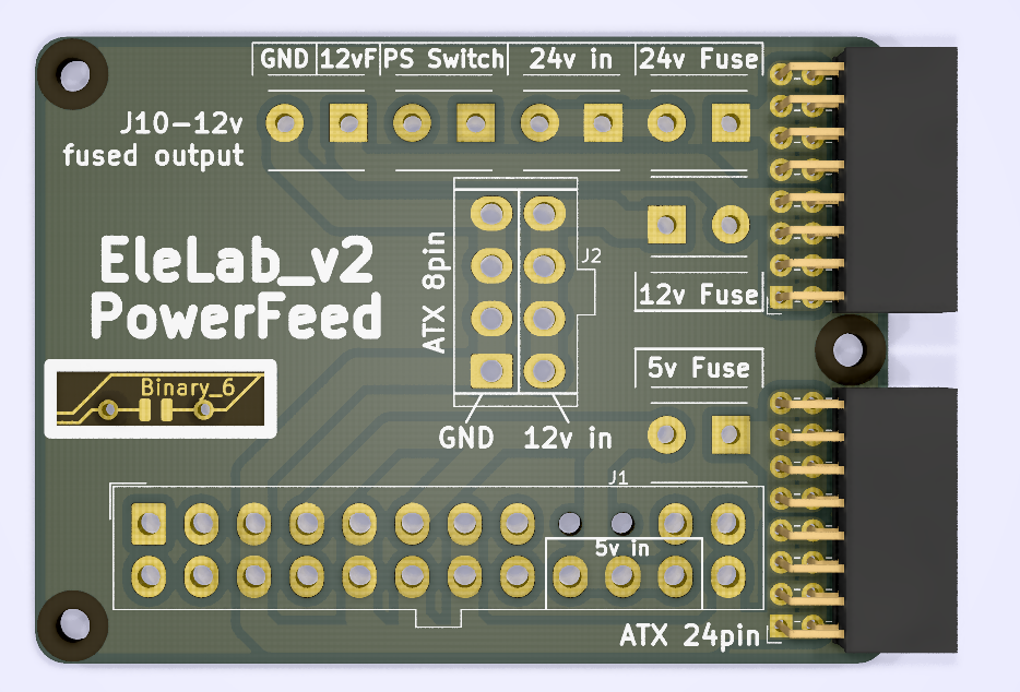
This is the main infeed to connect your power supply to the backpanel bus and feed into the modules. It packs jacks to plug in your SFX supply, screw connectors for external fuses, and a breakout for the SFXs standby switch. Alternatively you could wire up your supplies directly to the spots marked as 24V, 12V and 5V respectively without using ATX connectors.
Parts:
- 24 Pin 4.2mm ATX Connector standing
- 8 Pin 4.2mm ATX Connector standing
- 6pcs 5.08mm 2 Pin screw terminal (The blue cheap ones, optional though)
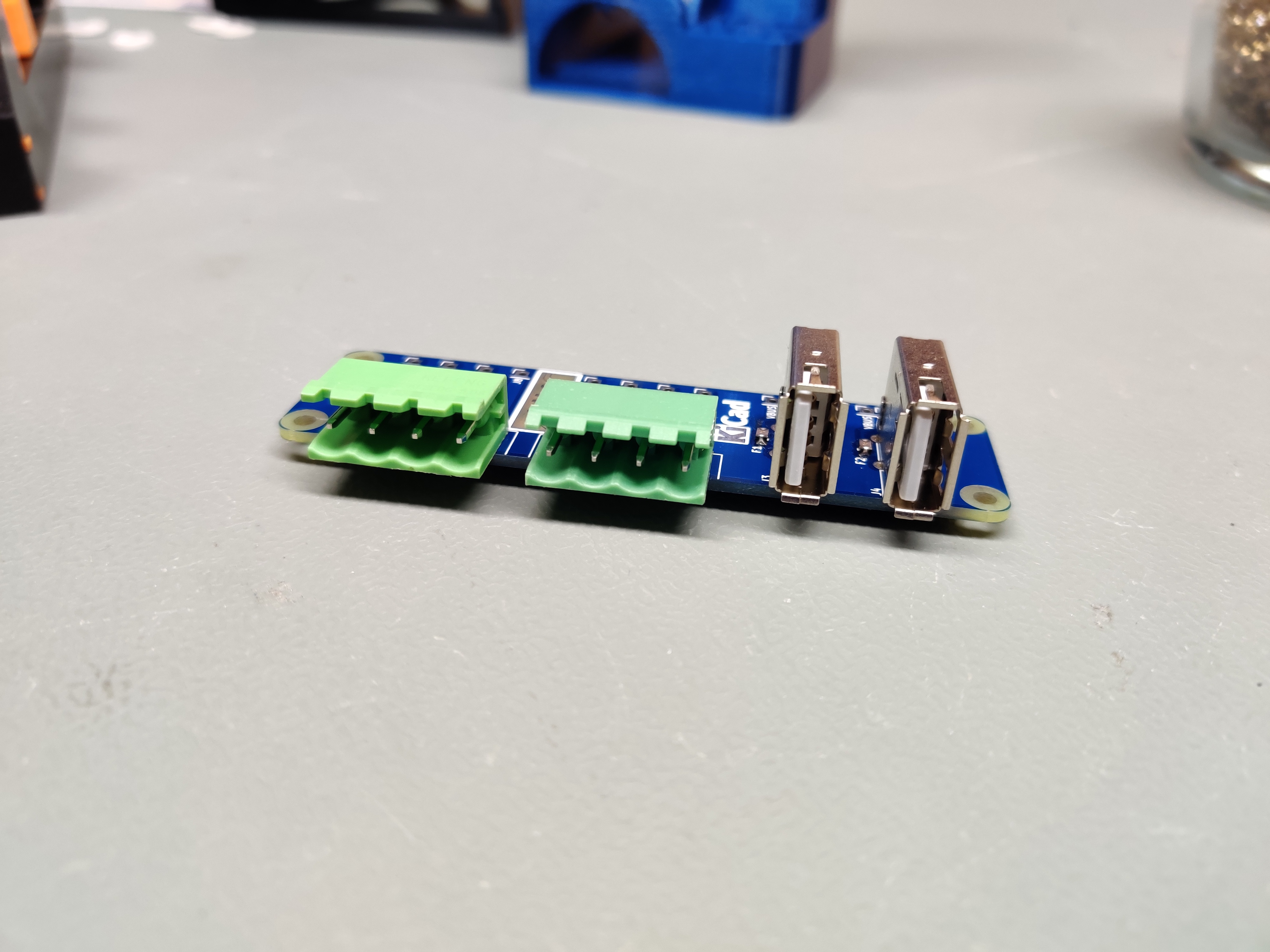
Here we have the basic front panel breakout with industry style screw-plug connectors and USB jacks. The USB Jacks have a 0805 footprint in line with the 5 V rail so you can optionally install a tiny polyfuse in there. The data lines of each USB port are broken out so you can either use it for normal data transfer, or do whatever the best quick charge port configuration on the data lines is today. (for example bridging D+ and D- to put old Android phones into quick charge mode)
Parts:
- 2pcs 5.08mm pcb screw terminal block 4 pin
- 2pcs standing vertical USB Ports
- 2pcs 0805 polyfuse 1.1A (Or your desired amperage)
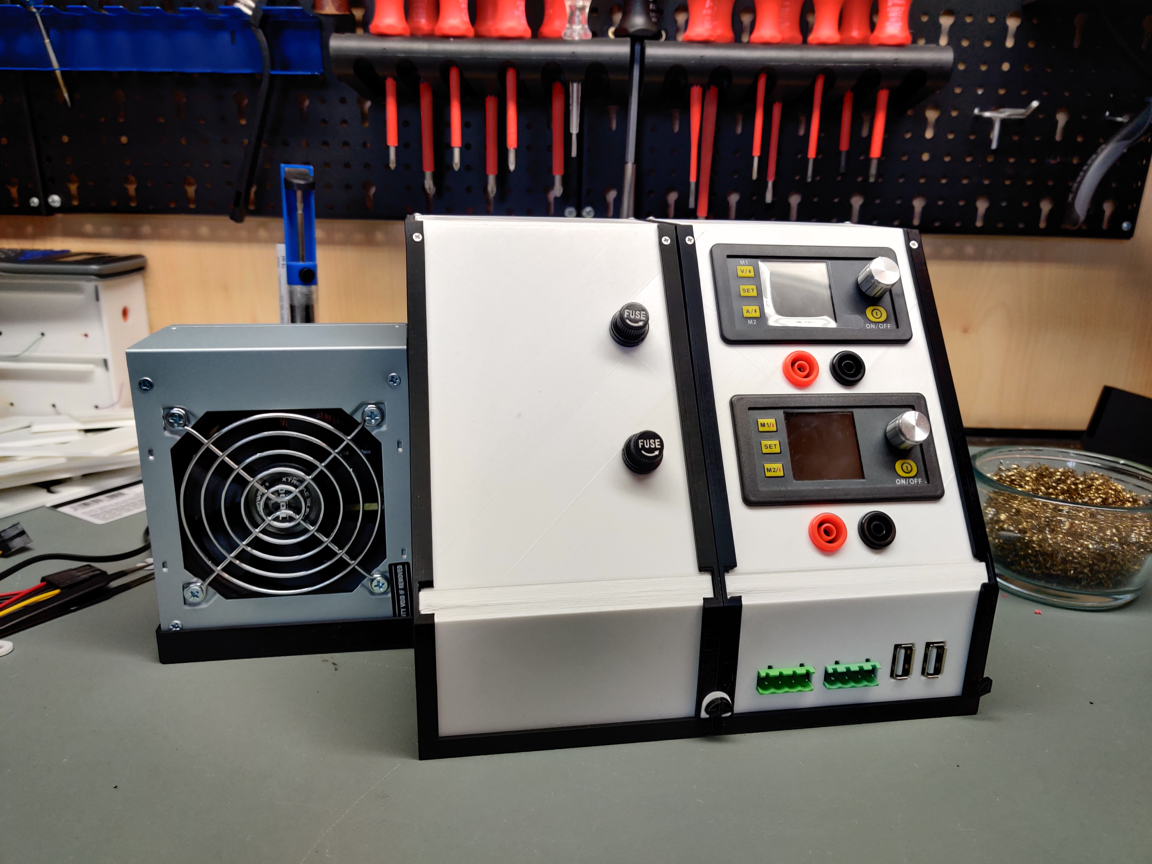
The easiest way to supply power to your EleLab is to use a regular ATX or SFX computer power supply. Using the PowerFeed PCB you can plug in the 24pin and 8pin connectors of your PSU directly into the backpanel bus. The module is preconfigured to use fuses for the 12 V and 5 V rails. You could install a switch for the PowerON PSU signal but i usually just bridge it completely so i switch the EleLab on and off by the main power switch on the back of the PSU.
Make sure the fan of your PSU is exposed as in the picture as not to overheat your poor PSU.
In the picture you see me build the SFX version of the module, the ATX version is printing at the time of writing this and is not tested yet.
Parts:
- PowerFeed PCB
- 2pcs screw in fuse holder panel mount
- SFX PSU of your choice
- 5pcs M2x8 self tapping screws
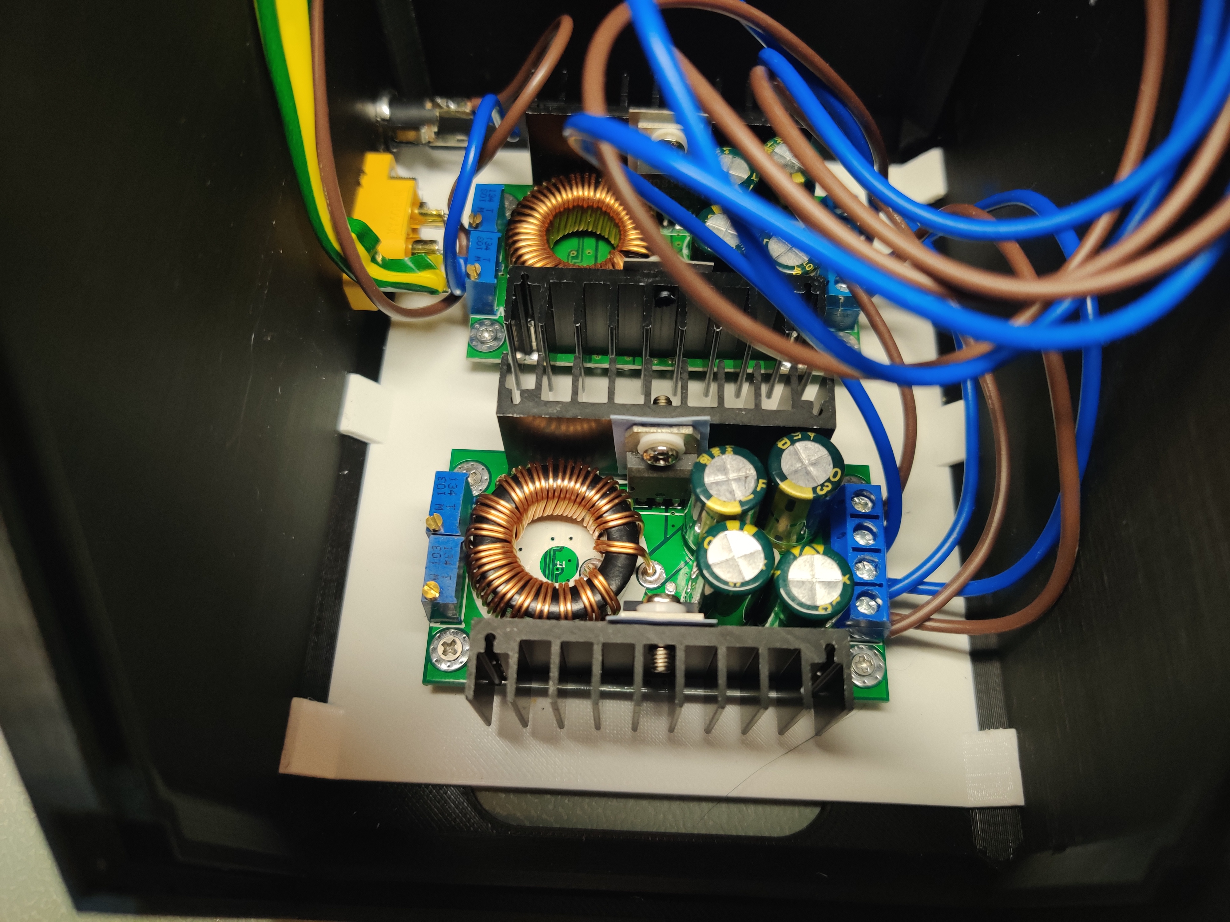
With this supply module you can use any external 12 V or 24 V Power supply you want. You could even plug in some batteries with the XT60 jack! This module however needs some beefy DC-DC step-down converters to create the 5 V rail, as well as the 12 V rail if you are using a 24 V supply. There is a printable tray that just snaps into the bottom, capable of carrying two of these types of step down converters:
These are readily available from china for a few bucks if you search for "step-down" on ebay.
One of the converters will be set to output 5 V and one to output 12 V, when you supply the module with 24 V DC. This will give you all 3 voltages on the backpanel bus.
Parts:
- PowerFeed PCB
- 3pcs screw in fuse holder panel mount
- 2pcs DC-DC Step down converters
- 9pcs M2x8 self tapping screws
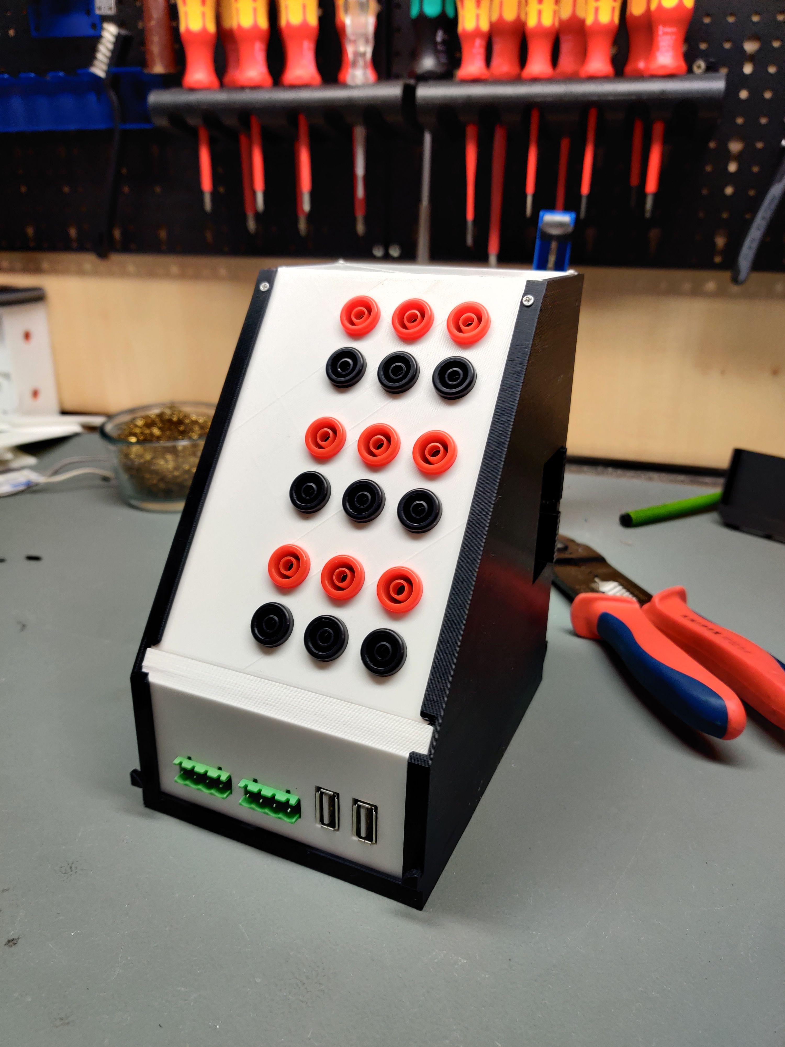
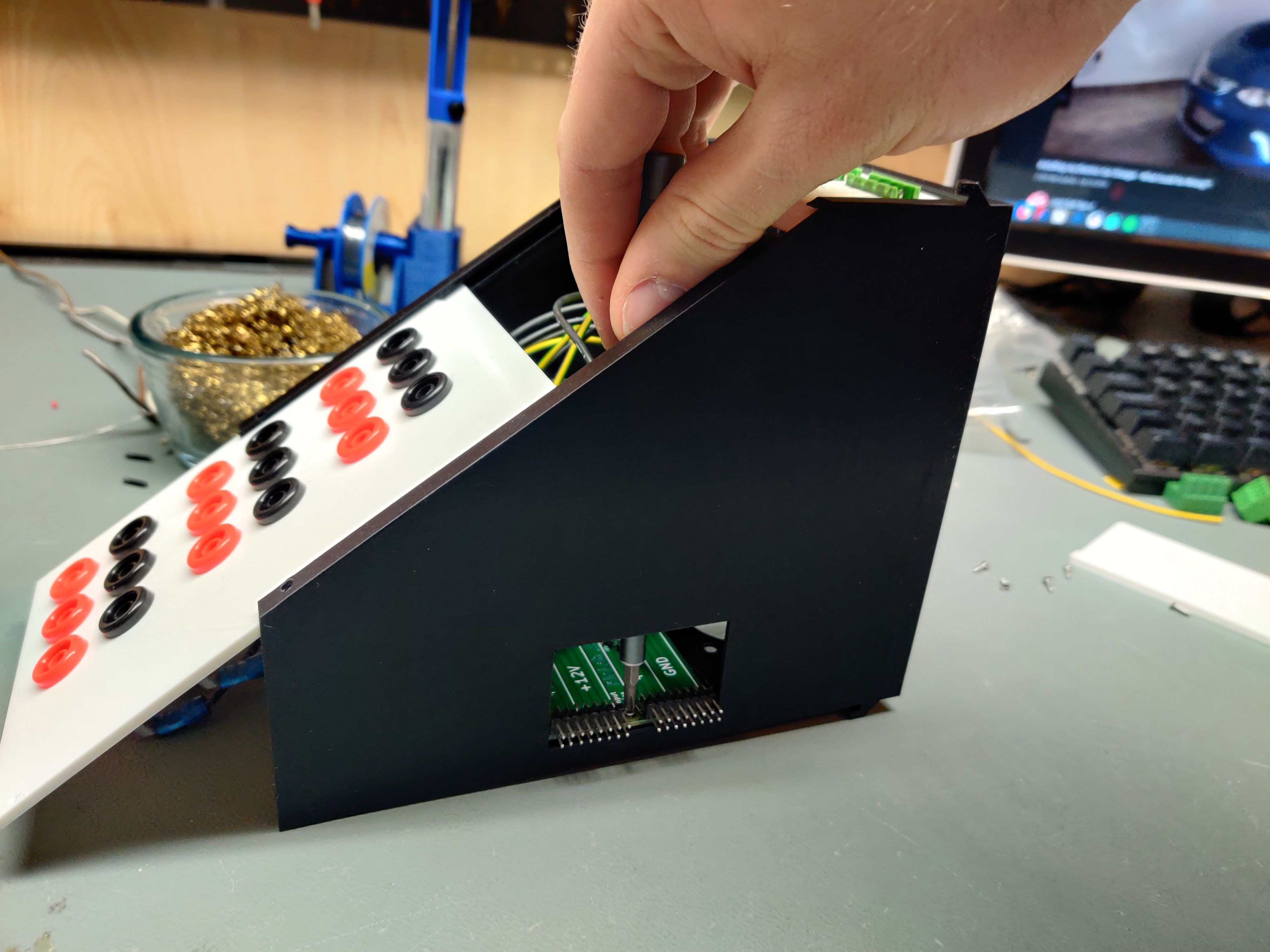
The first actually usable module is a power breakout for your 5 V, 12 V and optionally 24 V rails. Using cheap chinese banana jacks with 12mm OD all rails can be accessed. In the front we use the Frontpanel_a PCB to have connections beside the banana jacks. Which terminal you connect to which rail is only dependend on your preferences. Obviously make sure to not reverse polarity on the USB ports or risk frying something.
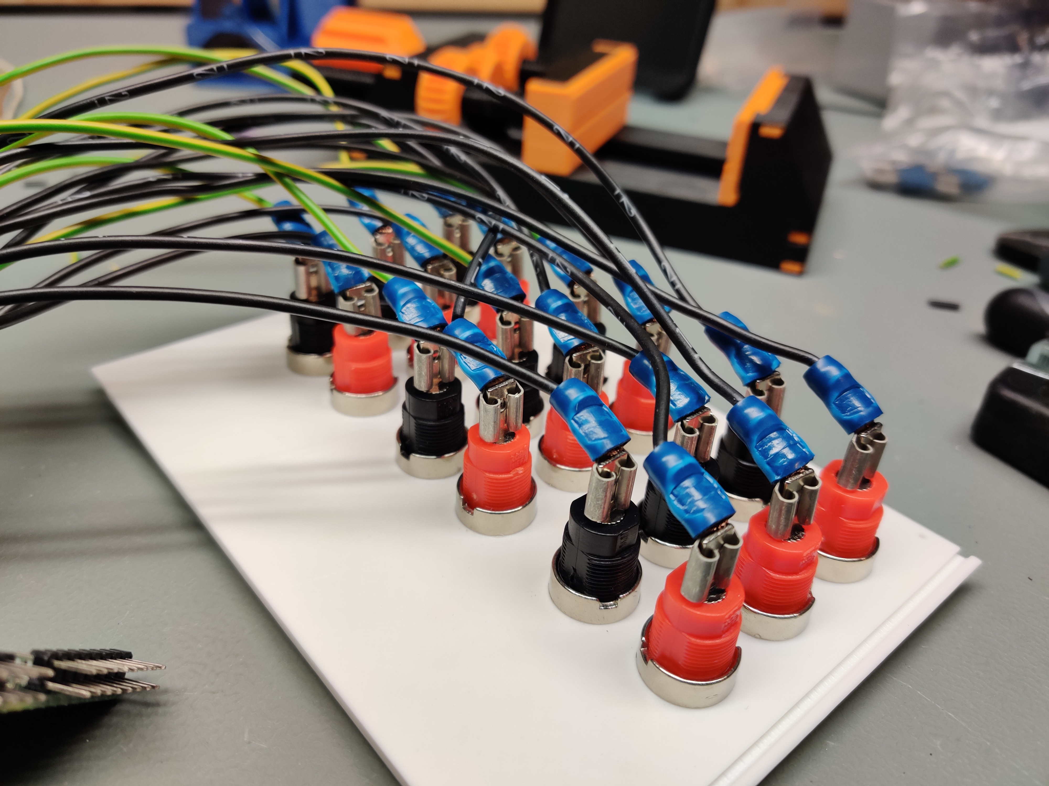
Here you can see the spagetthi wiring behind mine:
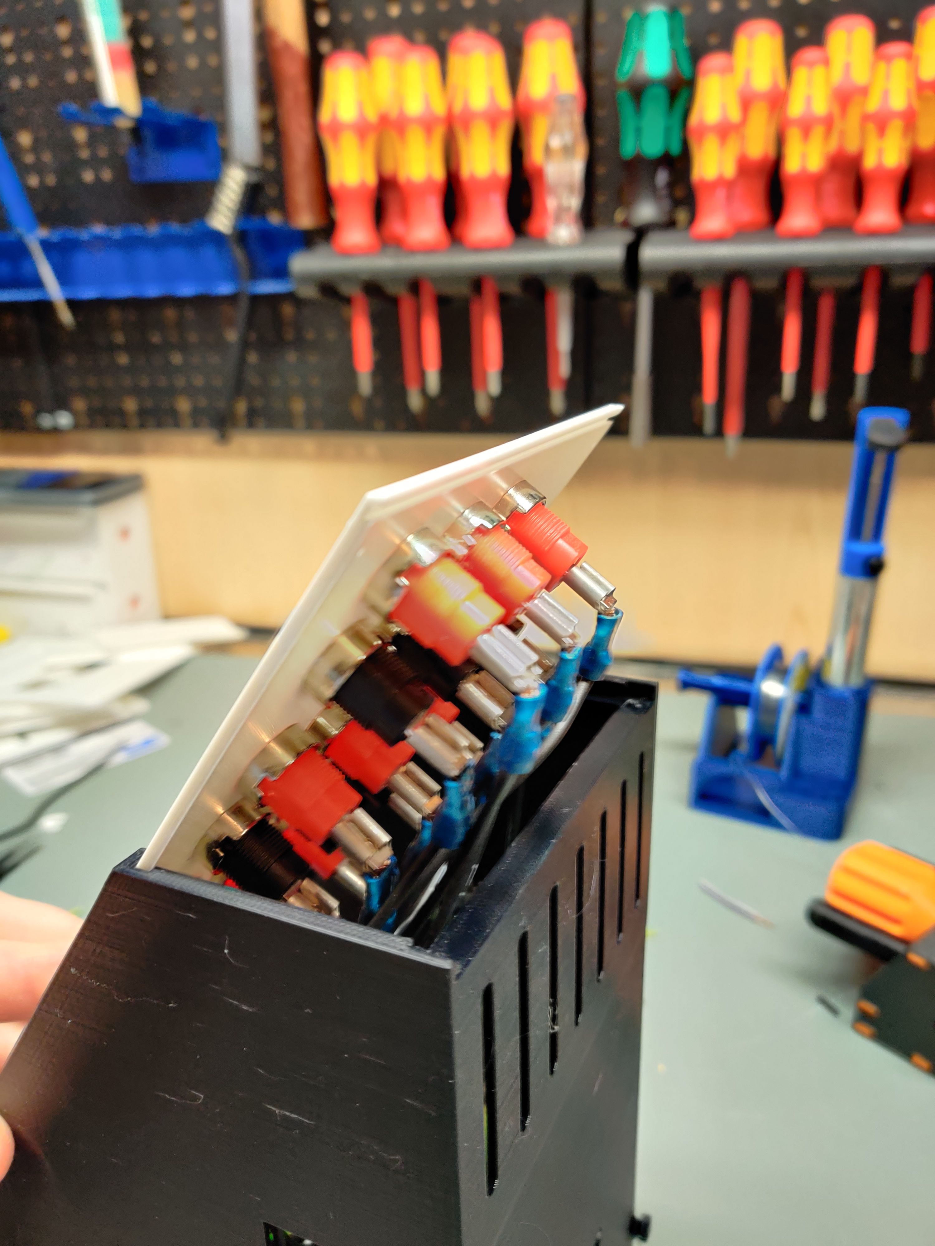
Be sure to bend over your connectors as seen here as there is not extremely much room for the upper front panel to slide down:
The banana jacks are intentionally uncentered to make room for labeling on the left. I did not have time to create printable labels yet but i will get to it.
Parts:
- 12 or 18pcs banana jacks
- Bus100 PCB
- Frontpanel_a PCB
- 10pcs M2x8 self tapping screws
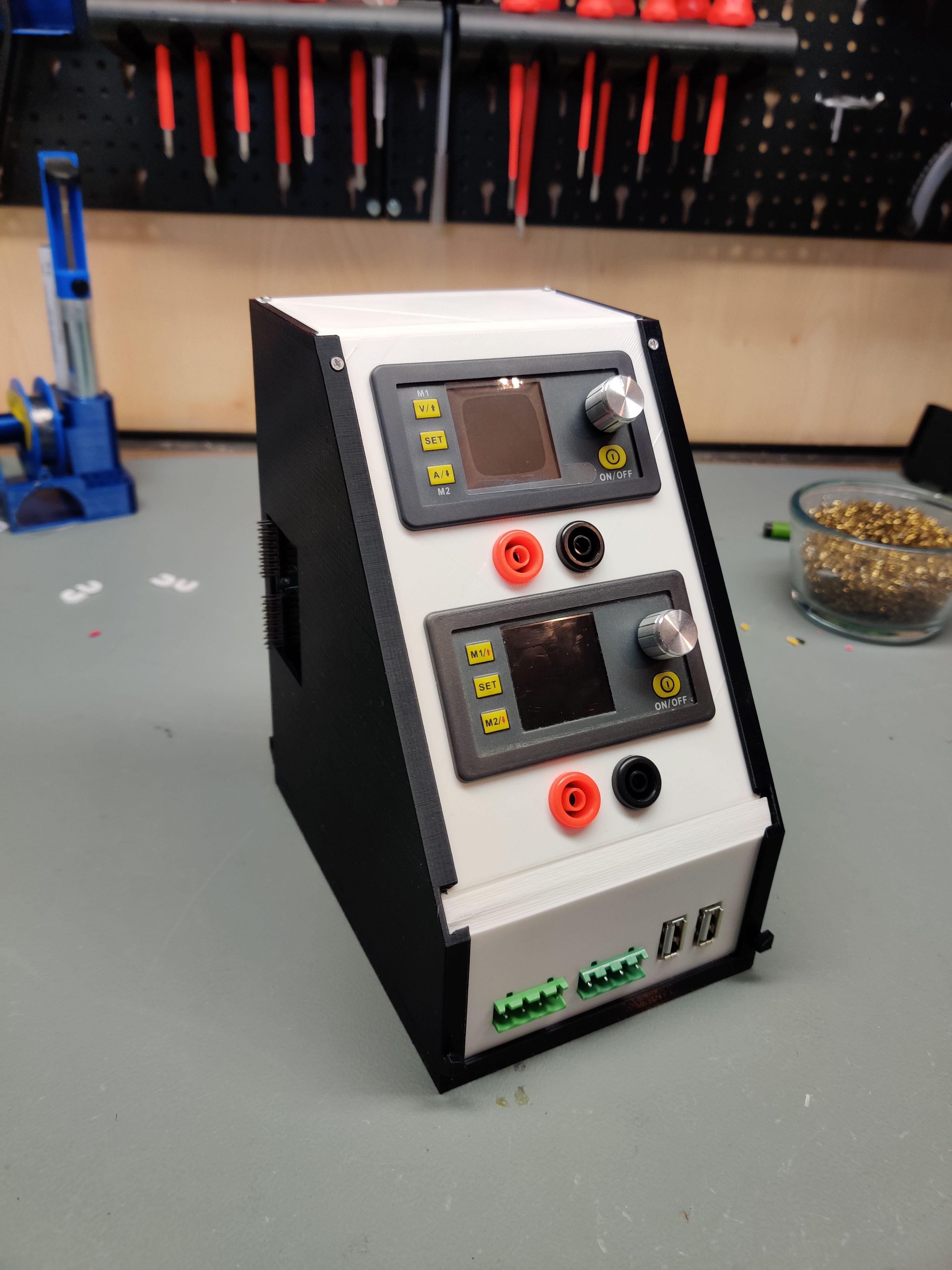
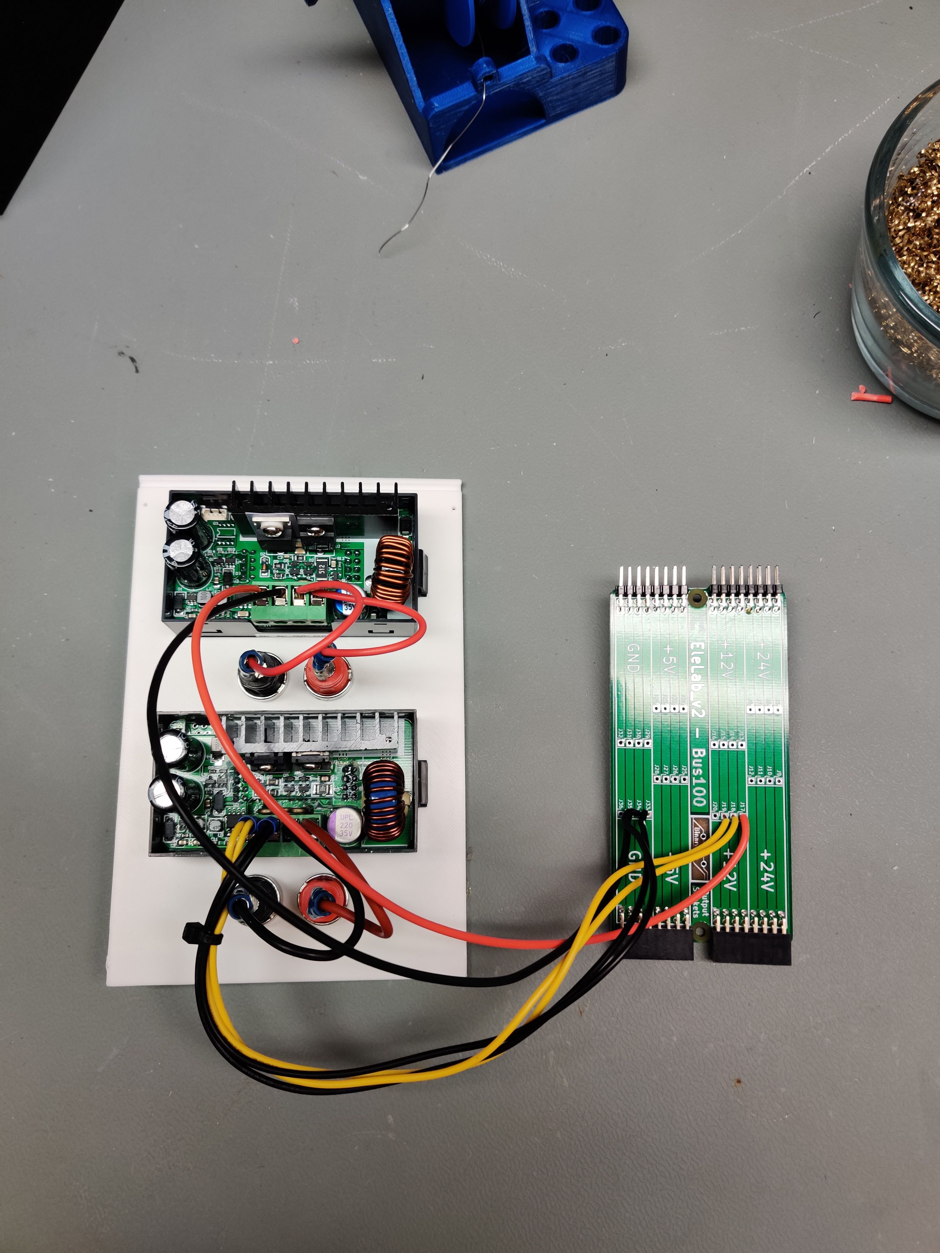
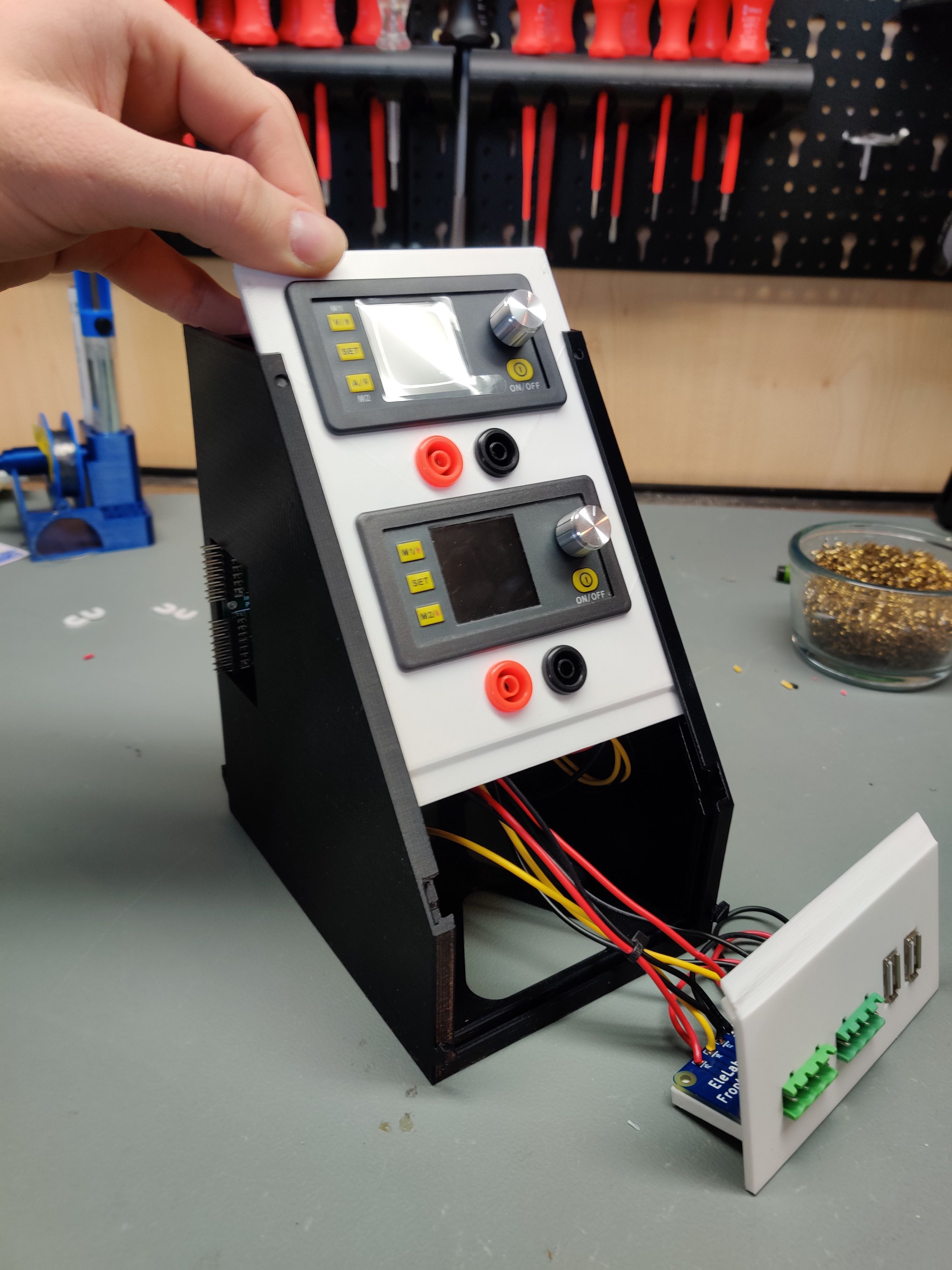
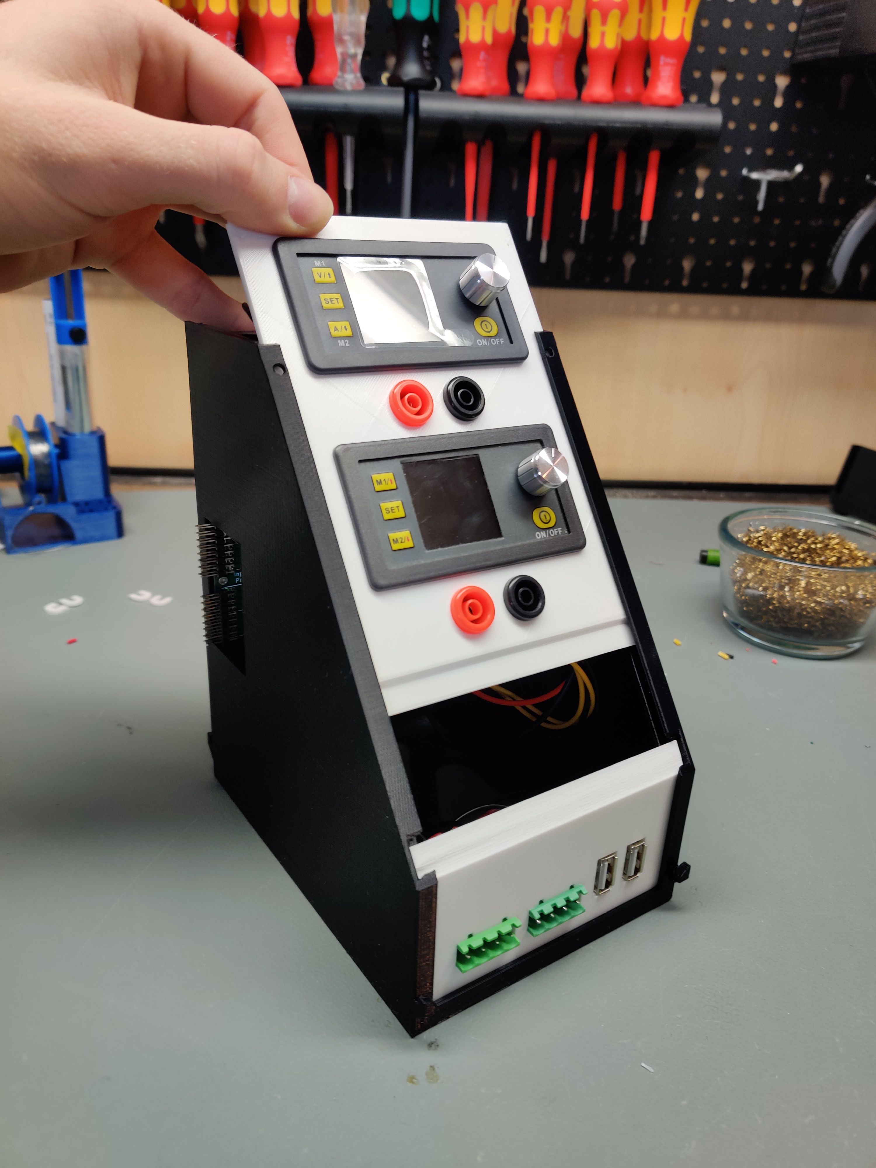
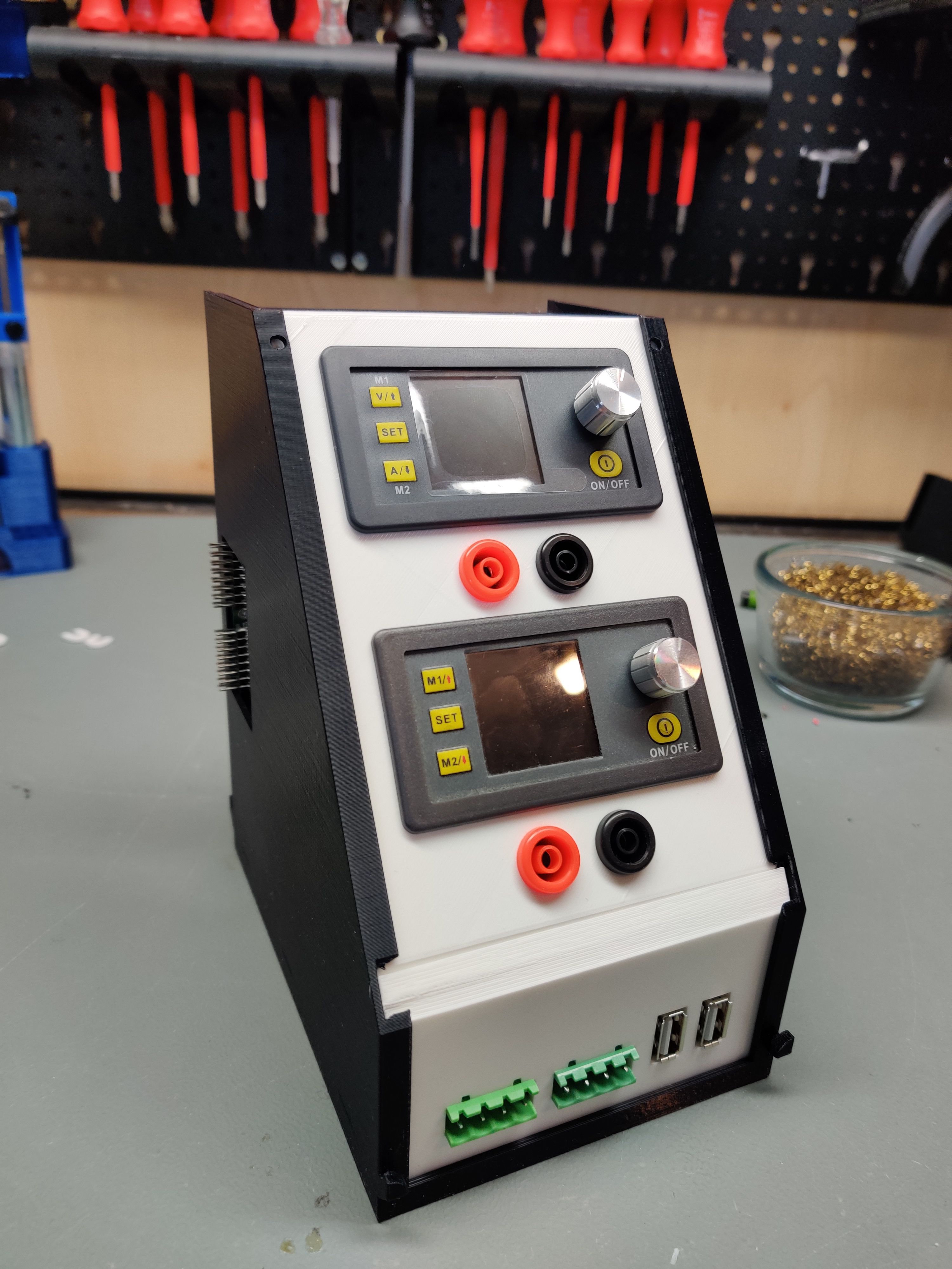
Similar to the fixed supply we use a Frontpanel_a PCB here. The two variable step down converters (ebay is your friend again, TBDnameOfStepDown) are fed by either the 24 V or 12 V rail, depending on your infeed capabilities. Under each converter i put two banana jacks as the output, but also in parallel i wire up the industrial screw-plug connectors in the front to be outputs as well. If you are feeling adventurous you can also but the USBs behind the converters, but be vary that you can potentially but up to 24 V through the USB port then if you tell the converter to do it. The USB Jack will not be a happy charging port but rather something for debugging.
Parts:
- 2pcs DPS30005 or similar step down converter. You can get these in all voltage ranges under different names.
- 4pcs banana jacks
- Bus100 PCB
- Frontpanel_a PCB
- 10pcs M2x8 self tapping screws
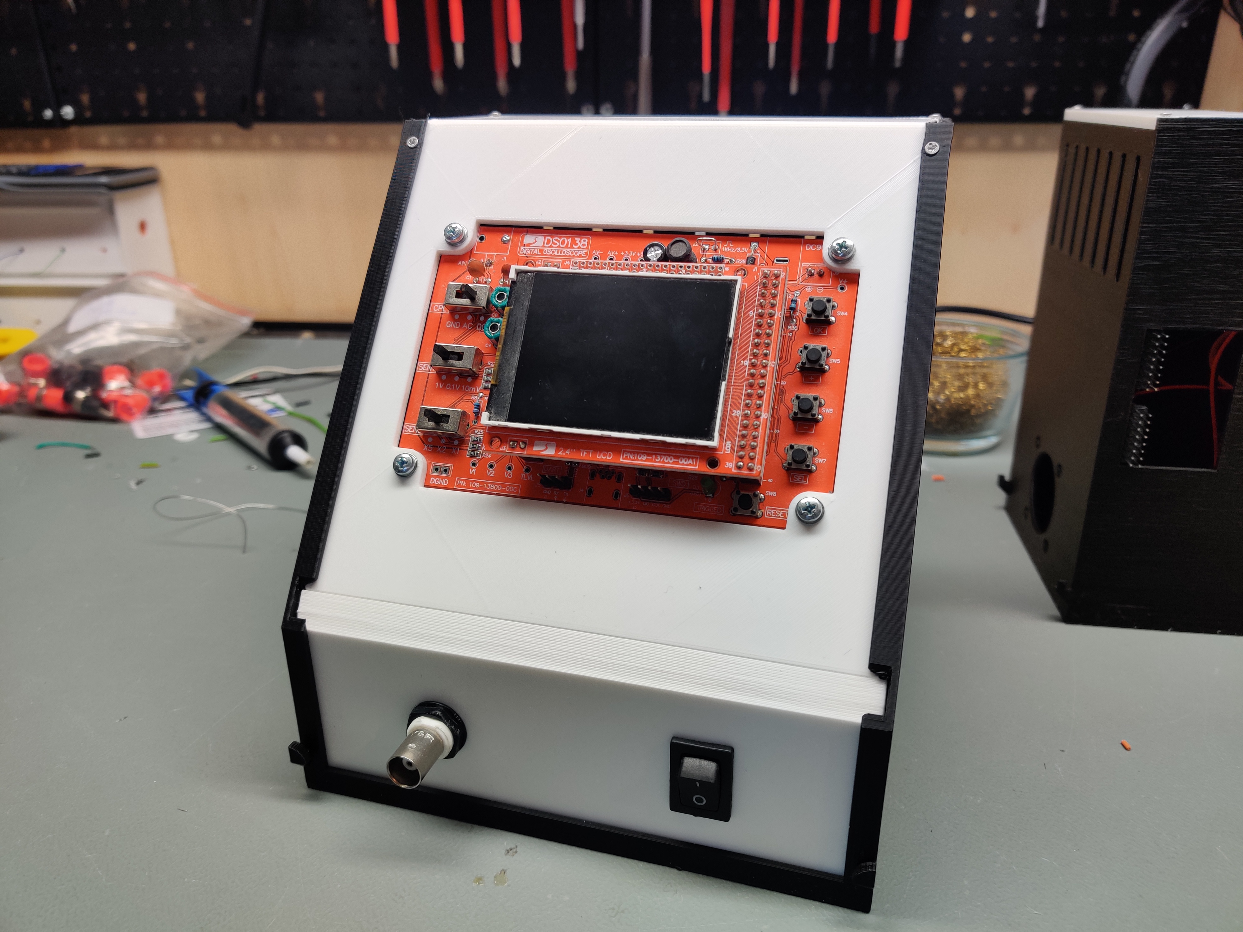
The DSO138 is a great "Babies first oscilloscope". This super cheap thing is awesome if you don't wanna shell out serious cash if you are going to look at simple waveforms once per year and don't really care about accuracy a lot. Oftentimes i just wanna know IF something is even executing code and don't care HOW it is doing it so i often still fire up the DSO138.
You have to remove the old power jack of the DSO138 PCB and feed in power through a 13mmx19mm rocker switch out of the 12 V rail for this to fit. 4 x M3 screws with nuts fix the DSO PCB into the panel from the back. The BNC jack is also removed, a new frontpanel screw-in BNC jack is installed in the front, and wired up to where the original jack was. This is best done with a shielded cable (though i doubt you will see much difference with a DSO of this quality..)
Parts:
- DSO138 kit
- 13mmx19mm rocker switch
- Bus150 PCB
- 4pcs M3 screws and nuts
- 6pcs M2x8 self tapping screws
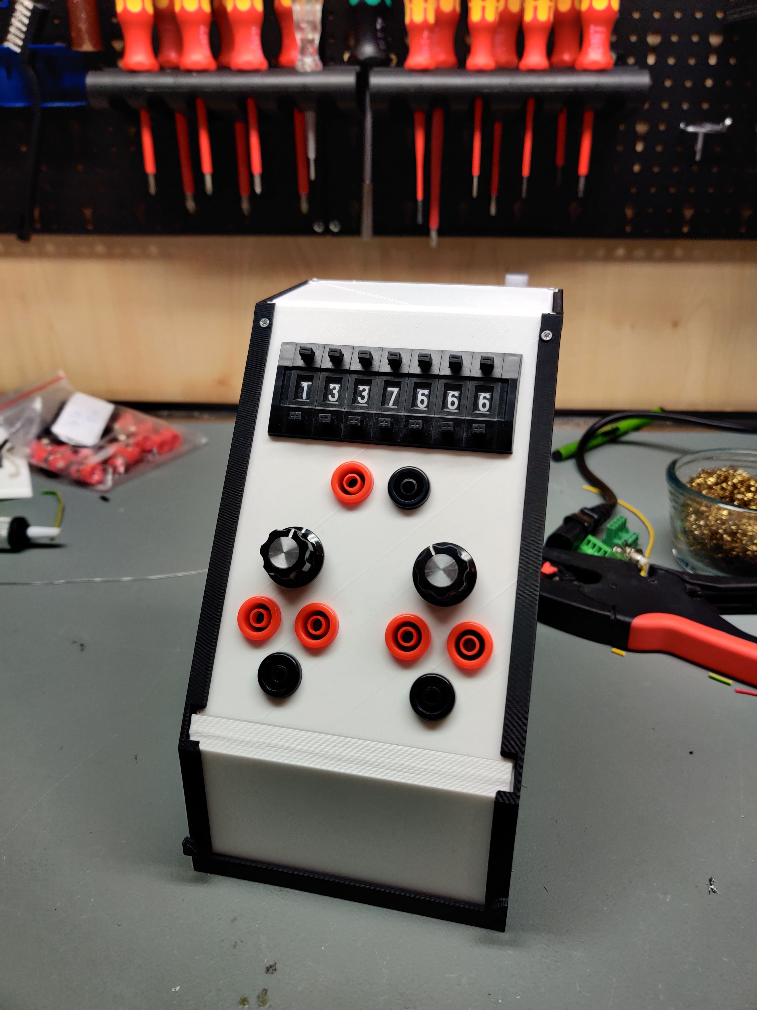
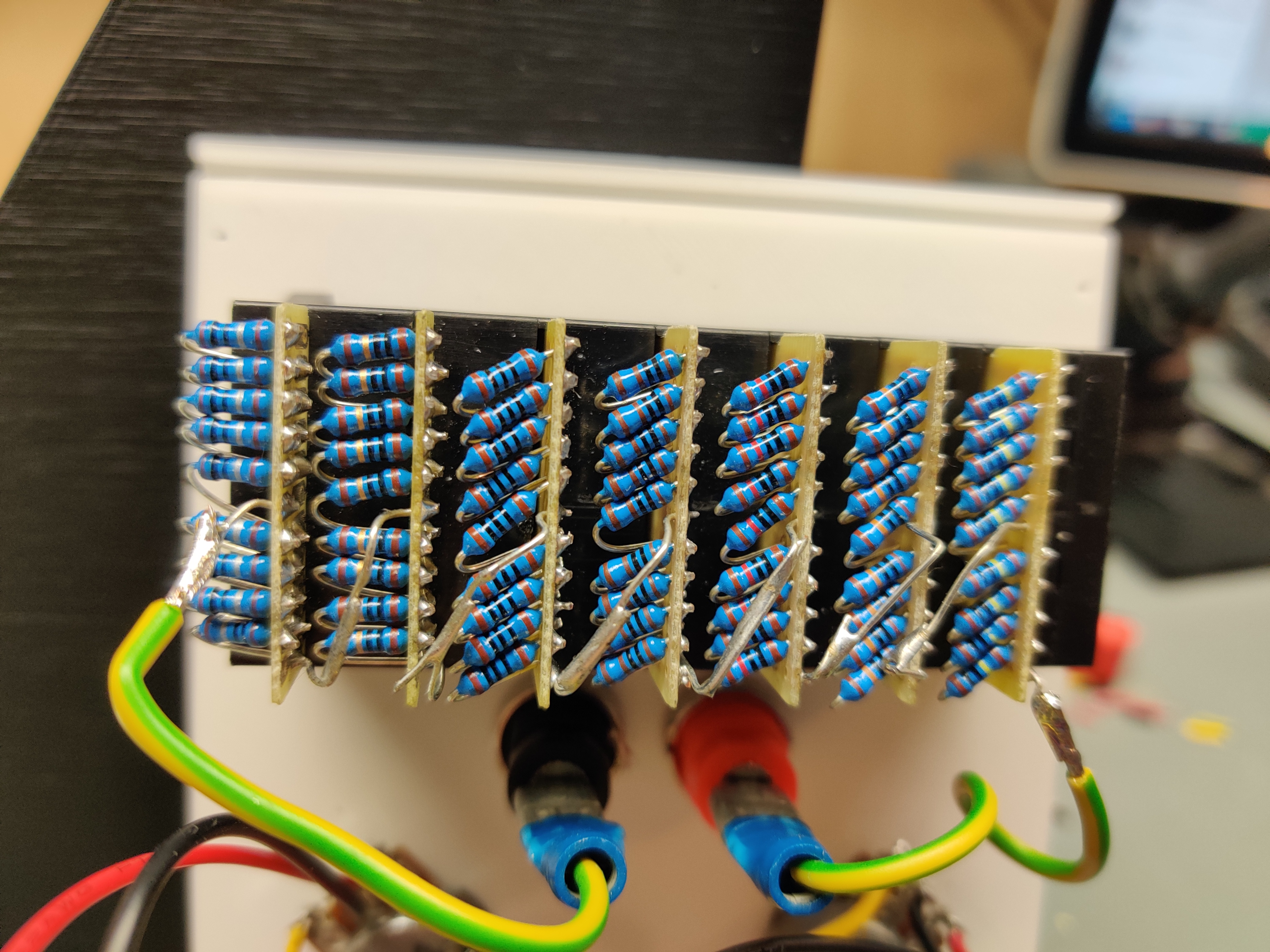
Not really needing a backpanel this can safely be placed as the last piece of the EleLab as it does not even require power. Please follow your favorite guide on how to wire up your decade.
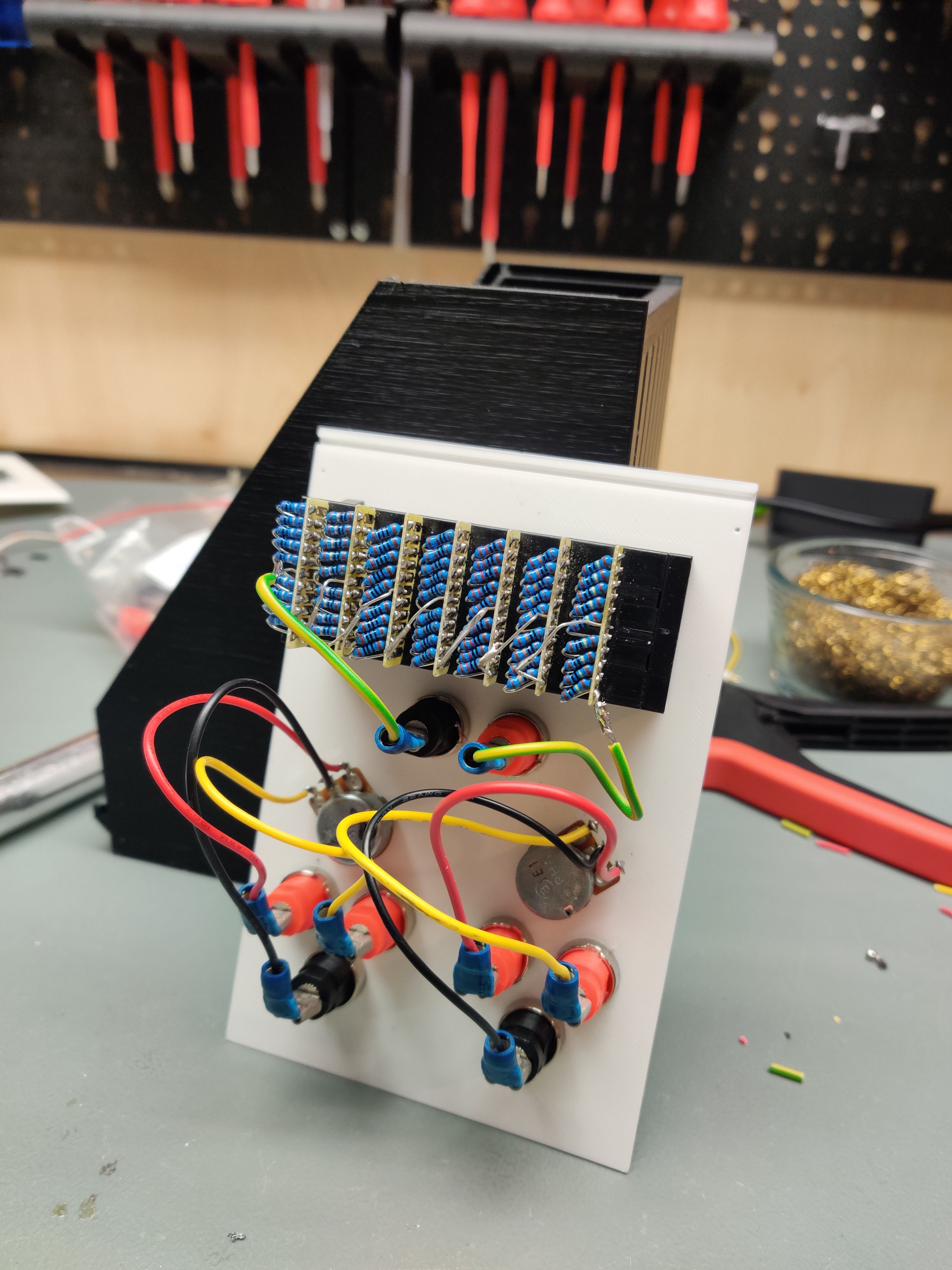
The 2 ends of the resistor decade are wired to two banana jacks. Also i installed 2 potentiometers into the panel, giving me some more flexibility. These are also just wired straight into 3 banana connectors.
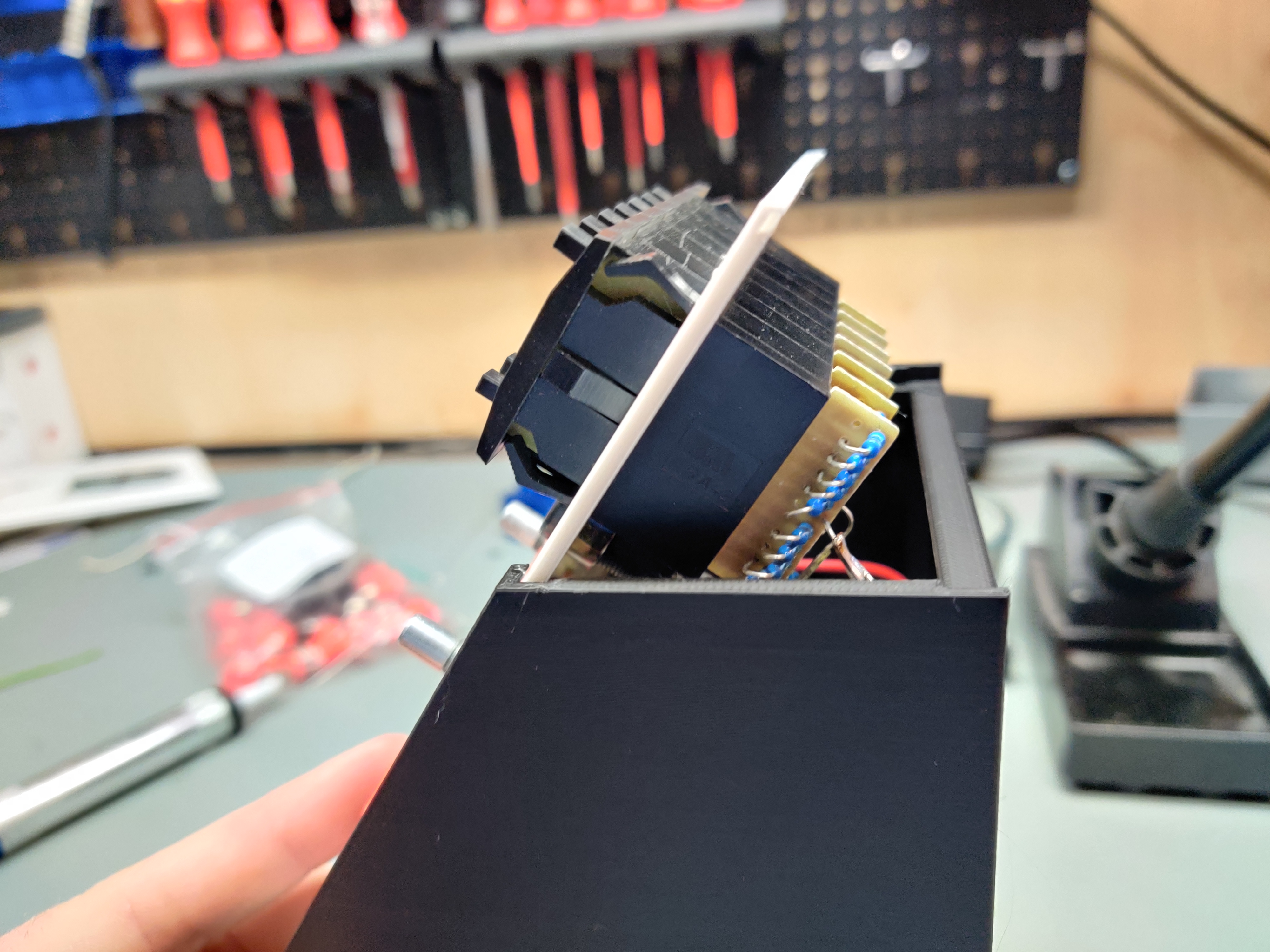
Closing this module is tricky as well. You will need to NOT snap in the decade before sliding the front panel down:
Parts:
- 7pcs Thumbwheel switches KSA-2 with the ending caps
- 9pcs each of 1, 10, 100, 1k, 10k, 100k and 1M Ohm reistor
- 2pcs 9mm potentiometers of your choice, i used 5K B and 25K B
- 8pcs banana jacks
- Bus100 PCB
- 4pcs M2x8 self tapping screws
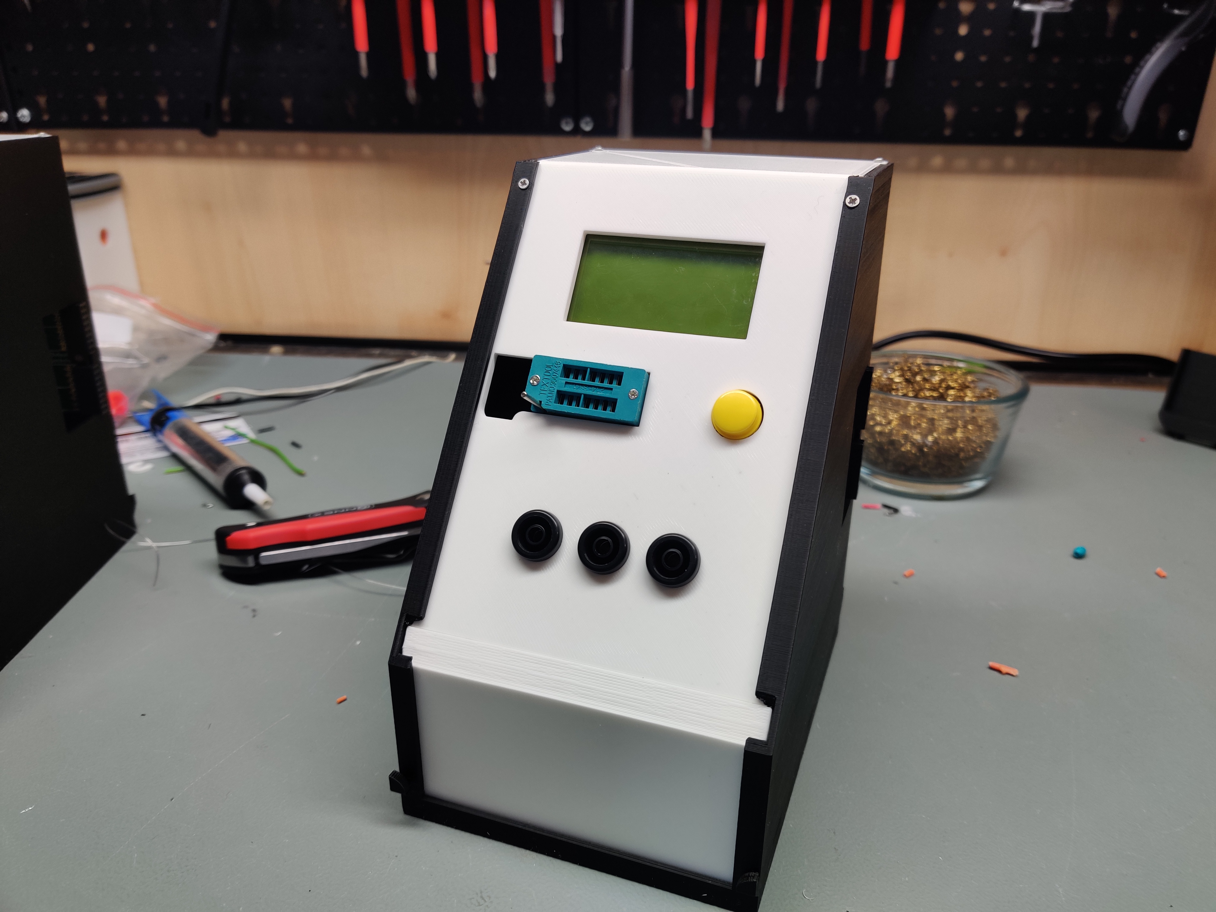
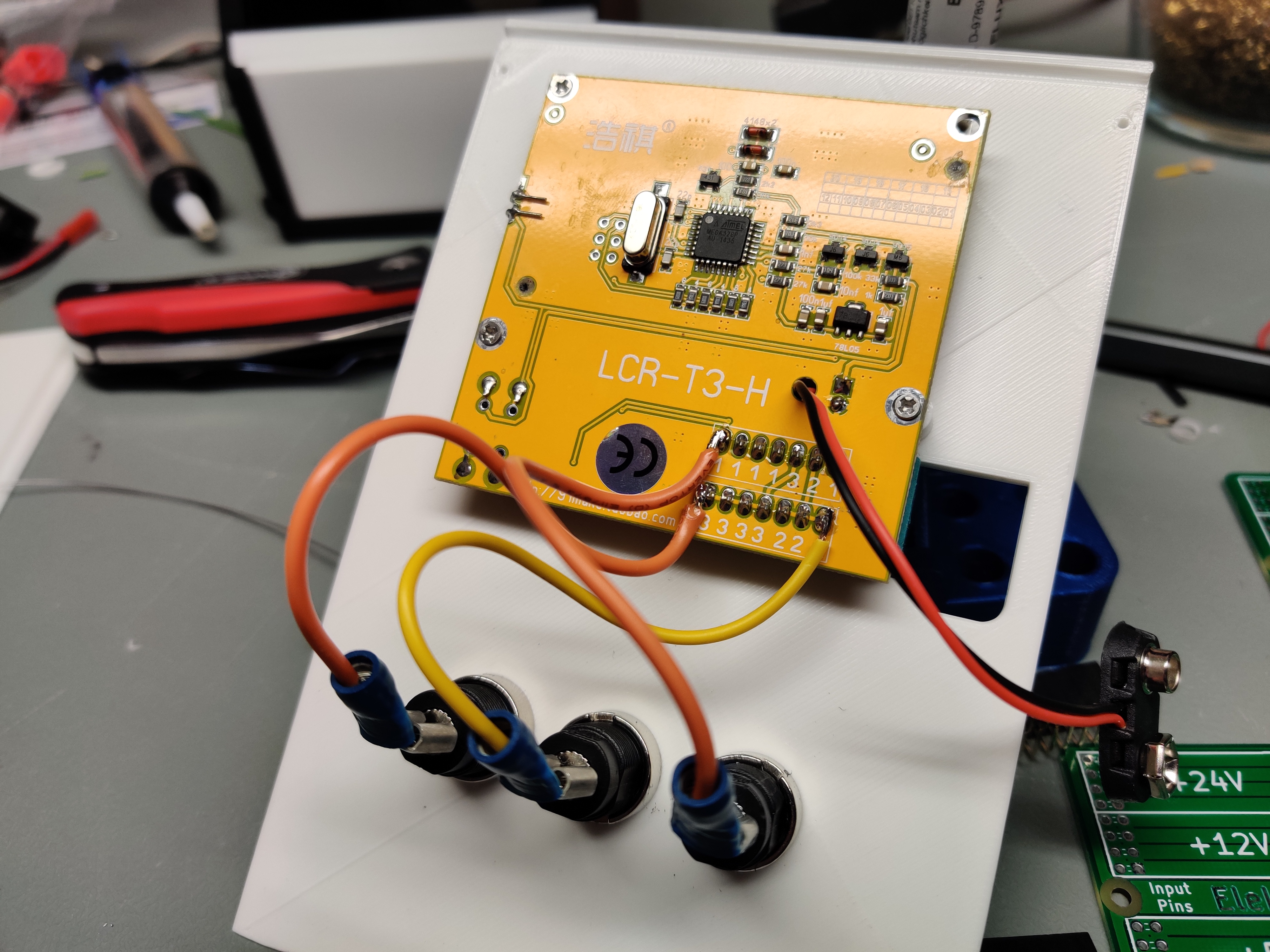
You would not believe how much utility you will get out of these things. They are also very cheaply ordered from ebay, screw into the upper panel from the backside and can identify almost all of the components you throw at it. Usually these are fed by a 9 V battery and while you could till do that and have a battery lying inside the module i just feed it from the 12 V rail. Don't know about any longterm damages though.
I wired 3 banana jacks right to the easiest to reach points numbered 1, 2 and 3.
Parts:
- Component Tester module
- 3pcs banana jacks
- Bus100 PCB
- 9pcs M2x8 self tapping screws
You can keep the wires nice and short if you put together the modules as follows:
The upper panel can be slid on now and the module is ready to be screwed together using two M2 screws each in the upper panel and the lid.
If you have really short cables running from your front panels to your backpanel bus you can also slide in the frontpanel first and only then screw the backpanel bus into the frame.
I am currently working on the following modules:
- Signal Tracer (Display and audio)
- Function Generator
- Epaper + ESP8266
- Solder sponge / wire holder + TS100 output
If you have an idea for other modules, go ahead, clone this repo and try creating your new module! Also be sure to upload it to thingiverse as a remix. If you don't know how to create a module yourself, feel free to send me a message!
If you like my work please consider supporting my caffeine addiction!
