
This is an example of how to use variants with KiBot.
In the KiBot context a variant is what is usually known as an assembly variant. So the idea is that you have one PCB, but various different variants (flavors) of the product. The difference between them is which components are used.
Typical applications are:
- Optional functionality
- Support for different normatives
- Testing purposes
Currently KiBot can handle not only which components are soldered, but also different values. The support for different values is complex and only used by a minority. So please be patient if some use case isn't well covered, just report it.
To create a variant you must add specific fields to the components in the schematic. Currently KiBot supports three methodes:
- KiBoM style: one field, usually named Config, contains information to include or exclude a component for one or more variants.
- KiCost style: one field assigns the component to one or more groups, you provide a regular expression to include certain groups.
- IBoM style: one field assigns the component to a group, you provide lists to exclude or include certain groups.
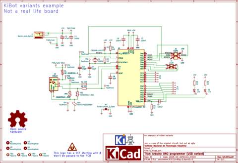
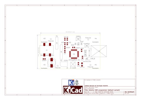
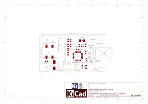
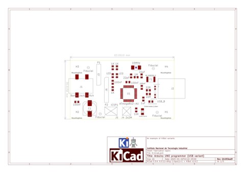
The best way to explain how to use it is using an example. We start with an hypothetic design: the programmer section of the Arduino UNO R3. The schematic is the following:
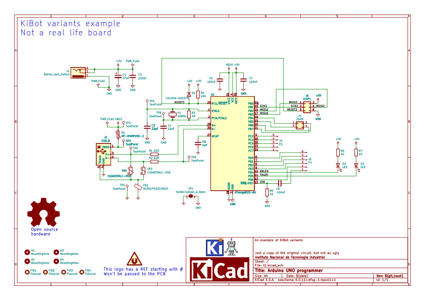
This is basically an ATMega8U2 used as a bridge between USB and the Arduino UNO serial port. So we will assume this board is useful. We'll also assume we have three possible uses:
- The full board with USB support. We'll name it USB variant.
- A version of the board that we want to use as a plain microcontroller. So we remove the USB. We'll name it XTAL variant.
- An even more modest version where we use the internal clock oscillator and we can remove the crystal. We'll name it default variant.
Additionally:
- In the USB version we want to remove the ICSP1 connector. We'll flash the CPU in-house and the user won't need to do it. ICPS1 will be solded for the other two variants.
- The J4 connector is completely optional. It won't be included in any variant.
The first step is to choose a variant mechanism. For this example we will use the KiBoM style. This style puts more information inside the schematic, so you need to provide less information from outside.
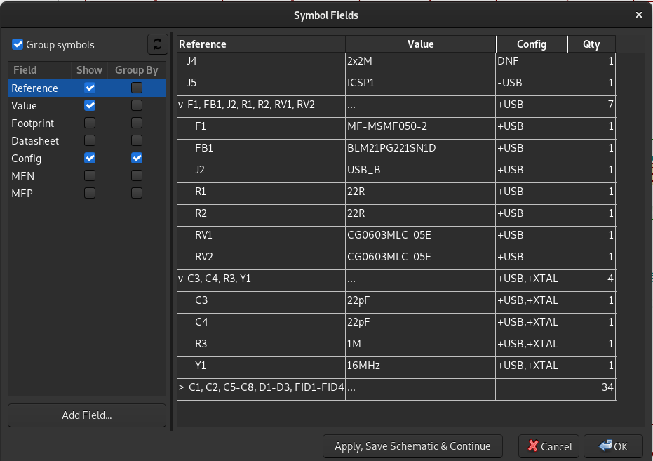
Now that we chose a format we must add the corresponding tags. We can identify four groups of components here:
- The USB components (J2, F1, R1, R2, RV1, RV2 and FB1). Used only for the USB variant.
- The ICSP1 connector (J5). Excluded from the USB variant.
- The crystal components (R3, Y1, C3, C4). Used only for the USB and XTAL variants.
- The 2x2M connector (J4). Never used.
To mark components that will be added to the board only for certain variant KiBoM uses +VARIANT. And when we want to exclude a component from a variant we use -VARIANT.
We'll use the default Config field. So lets see what we'll use for each group.
- For the USB components we'll use +USB because these components will be used only for the USB variant.
- For the ICSP1 connector we'll use -USB because this component will be solded for all variants, except USB.
- Now the crystal stuff is a little bit more complex. We could use +XTAL, but then these components won't be included in the USB version. So what we use is +USB,+XTAL this makes the components available for both variants.
- The J4 case is handled in a different way. KiBoM filters removes any component mentioning the DNF word in the config. So we can just use it.
Now that we know what to use we'll add the Config field to the mentioned components. To make it faster we can add it to one component, lets say to J4, and then use the Tools -> Edit symbol fields menu option. Here is what we should have in the Config field:
This is all we need to add to the schematic. Now is time to configure KiBot.
If you don't know about the KiBot file format you could be interested in reading the following explanation. YAML files are self explanatory, so perhaps you can go on even without knowing about the format.
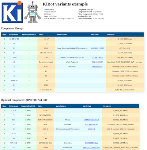
Ok, now we have to define the three variants we mentioned before: USB, XTAL and default. All variants will be put in a section named variants. So we'll create a list of items, each item is a variant definition. Lets start with the simplest: default. Here is what we use:
variants:
  - name: 'default'
    comment: 'Minimal PCB no USB'
    type: kibom
This is the section variants and its first item. The name is default and we added a comment to remmember what this variant is. We also define the type as kibom, what we called style.
Now lets go for the second, here we add:
  - name: 'USB'
    comment: 'Full board'
    type: kibom
    file_id: _USB
    variant: USB
You'll notice two new attributes: file_id and variant. The first is what we'll add to the names of the files in order to distinguish from the default.
And the second ... well this is just the tag we used to mark USB components.
You should be able to figure out how to define the third variant, here we go:
  - name: 'XTAL'
    comment: 'No USB, but crystal included'
    type: kibom
    file_id: _XTAL
    variant: XTAL
A little bit long, but simple. Here is all together:
variants:
  - name: 'default'
    comment: 'Minimal PCB no USB'
    type: kibom

  - name: 'USB'
    comment: 'Full board'
    type: kibom
    file_id: _USB
    variant: USB

  - name: 'XTAL'
    comment: 'No USB, but crystal included'
    type: kibom
    file_id: _XTAL
    variant: XTAL
This is all we need to define the variants. Of course our config file must define what to do with the variants. But this document is about the variants, we won't focuse on the rest. You can see the whole configuration file here.
What now? How can we tell KiBot what variant to use? There are three methodes:
- Use the
variantoption for an specific output. - Select a default variant to be used by all outputs that doesn't specify a variant.
- Same as above but from the command line.
The simplest way is the third. In this case we just need to add -g variant=NAME to the command line.
Lets say we have a copy of the repo containing this example and we want to generate the BoM.
In our example the HTML BoM output is named bom_html so we can just run:
kibot -s run_erc,run_drc -d Result bom_htmlThis will create Result/BoM/t1-bom.html. To generate the BoM for the USB variant we can use:
kibot -s run_erc,run_drc -d USB -g variant=USB bom_htmlAnd we'll get a different BoM in USB/BoM/t1-bom_USB.html.
The CI/CD workflow for this repo runs the ERC and DRC checks and then generates all the configured outputs for the three variants. The commands used are approximately these:
kibot -d Generated -s run_drc -i
kibot -d Generated -s run_erc -i
kibot -d Generated/default -g variant=default -s run_erc,run_drc
kibot -d Generated/USB -g variant=USB -s run_erc,run_drc
kibot -d Generated/XTAL -g variant=XTAL -s run_erc,run_drc
The first two are the checks, no output generated. The other three skips the checks and generates all outputs for each variant.
All files are stored in the Generated folder.
Here is what we get, you can download the results obtained on GitHub CI/CD Actions from here. Click on the images to get a larger image or the generated document.
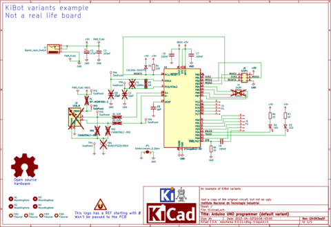
Excluded components are marked with a cross:
- Default variant
- XTAL variant
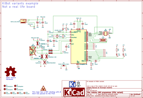
- USB variant
Excluded components are listed as DNF in a separated list. Note we could also remove them.
- Default variant
- XTAL variant
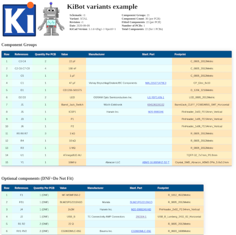
- USB variant
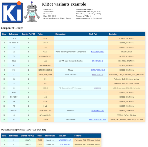
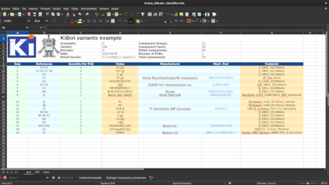
The XLSX files contain the same information, arranged a little bit different, here is the USB variant:
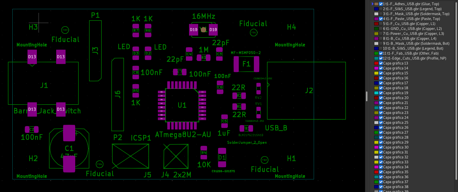
Excluded components are marked with a cross in the *.Fab layer. Their solder paste and adhesive glue is removed from *.Paste and *.Adhes. The following PDFs were gnerated including F.Fab, F.Paste, F.Adhes and Dwgs.User:
- Default variant
- XTAL variant
- USB variant
Excluded components are marked with a cross in the *.Fab layer. Their solder paste and adhesive glue is removed from *.Paste and *.Adhes:
- Default variant
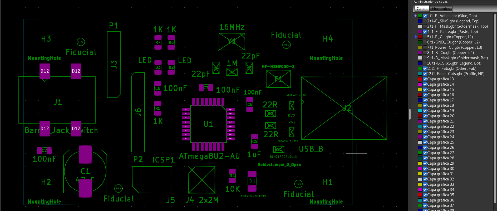
- XTAL variant
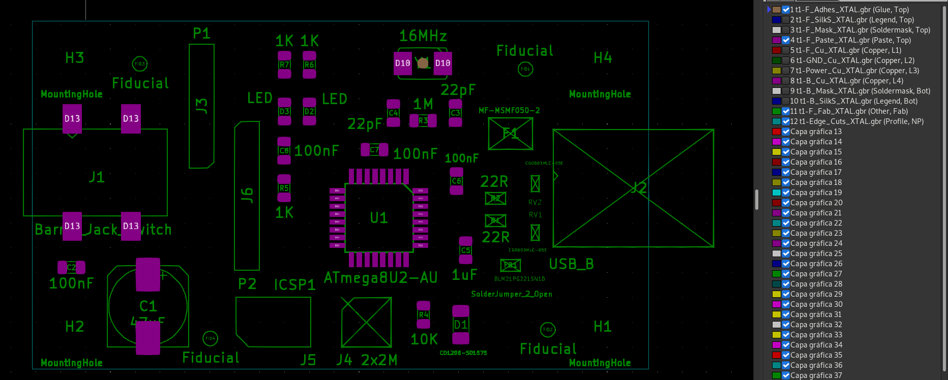
- USB variant
Here only the fitted components are included in the pick and place file:
- Default variant
### Module positions - created on Thu 10 Sep 2020 20:10:57  ###
### Printed by KiBot
## Unit = mm, Angle = deg.
## Side : both
# Ref   Val                  Package                                     PosX       PosY       Rot        Side
C1     47uF                 CP_Elec_8x10                                130.8354   -94.8944   270.0000   top
C2     100nF                C_0805_2012Metric                           123.0000   -90.9000   0.0000     top
C5     1uF                  C_0805_2012Metric                           163.3220   -89.1540   270.0000   top
C6     100nF                C_0805_2012Metric                           162.3822   -82.0674   90.0000    top
C7     100nF                C_0805_2012Metric                           153.9748   -78.8670   0.0000     top
C8     100nF                C_0805_2012Metric                           144.7546   -78.9686   90.0000    top
D1     CD1206-S01575        D_1206_3216Metric                           162.8140   -96.7740   90.0000    top
D2     LED                  LED_0805_2012Metric                         147.3200   -74.9500   90.0000    top
D3     LED                  LED_0805_2012Metric                         144.7800   -74.9500   90.0000    top
J1     Barrel_Jack_Switch   BarrelJack_CLIFF_FC681465S_SMT_Horizontal   126.1000   -81.2000   0.0000     top
R4     10K                  R_0805_2012Metric                           159.0040   -95.7580   90.0000    top
R5     1K                   R_0805_2012Metric                           144.7546   -82.8040   270.0000   top
R6     1K                   R_0805_2012Metric                           147.3200   -70.1748   270.0000   top
R7     1K                   R_0805_2012Metric                           144.7800   -70.1748   270.0000   top
U1     ATmega8U2-AU         TQFP-32_7x7mm_P0.8mm                        154.4320   -85.8520   270.0000   top
## End
- XTAL variant
### Module positions - created on Thu 10 Sep 2020 20:11:59  ###
### Printed by KiBot
## Unit = mm, Angle = deg.
## Side : both
# Ref   Val                  Package                                     PosX       PosY       Rot        Side
C1     47uF                 CP_Elec_8x10                                130.8354   -94.8944   270.0000   top
C2     100nF                C_0805_2012Metric                           123.0000   -90.9000   0.0000     top
C3     22pF                 C_0805_2012Metric                           162.2600   -75.1160   270.0000   top
C4     22pF                 C_0805_2012Metric                           155.9100   -75.1160   270.0000   top
C5     1uF                  C_0805_2012Metric                           163.3220   -89.1540   270.0000   top
C6     100nF                C_0805_2012Metric                           162.3822   -82.0674   90.0000    top
C7     100nF                C_0805_2012Metric                           153.9748   -78.8670   0.0000     top
C8     100nF                C_0805_2012Metric                           144.7546   -78.9686   90.0000    top
D1     CD1206-S01575        D_1206_3216Metric                           162.8140   -96.7740   90.0000    top
D2     LED                  LED_0805_2012Metric                         147.3200   -74.9500   90.0000    top
D3     LED                  LED_0805_2012Metric                         144.7800   -74.9500   90.0000    top
J1     Barrel_Jack_Switch   BarrelJack_CLIFF_FC681465S_SMT_Horizontal   126.1000   -81.2000   0.0000     top
R3     1M                   R_0805_2012Metric                           158.9580   -75.8780   180.0000   top
R4     10K                  R_0805_2012Metric                           159.0040   -95.7580   90.0000    top
R5     1K                   R_0805_2012Metric                           144.7546   -82.8040   270.0000   top
R6     1K                   R_0805_2012Metric                           147.3200   -70.1748   270.0000   top
R7     1K                   R_0805_2012Metric                           144.7800   -70.1748   270.0000   top
U1     ATmega8U2-AU         TQFP-32_7x7mm_P0.8mm                        154.4320   -85.8520   270.0000   top
Y1     16MHz                Crystal_SMD_Abracon_ABM3-2Pin_5.0x3.2mm     158.9278   -70.0278   180.0000   top
## End
- USB variant
### Module positions - created on Thu 10 Sep 2020 20:11:27  ###
### Printed by KiBot
## Unit = mm, Angle = deg.
## Side : both
# Ref   Val                  Package                                     PosX       PosY       Rot        Side
C1      47uF                 CP_Elec_8x10                                130.8354   -94.8944   270.0000   top
C2      100nF                C_0805_2012Metric                           123.0000   -90.9000   0.0000     top
C3      22pF                 C_0805_2012Metric                           162.2600   -75.1160   270.0000   top
C4      22pF                 C_0805_2012Metric                           155.9100   -75.1160   270.0000   top
C5      1uF                  C_0805_2012Metric                           163.3220   -89.1540   270.0000   top
C6      100nF                C_0805_2012Metric                           162.3822   -82.0674   90.0000    top
C7      100nF                C_0805_2012Metric                           153.9748   -78.8670   0.0000     top
C8      100nF                C_0805_2012Metric                           144.7546   -78.9686   90.0000    top
D1      CD1206-S01575        D_1206_3216Metric                           162.8140   -96.7740   90.0000    top
D2      LED                  LED_0805_2012Metric                         147.3200   -74.9500   90.0000    top
D3      LED                  LED_0805_2012Metric                         144.7800   -74.9500   90.0000    top
F1      MF-MSMF050-2         R_1812_4532Metric                           167.8940   -77.2160   0.0000     top
FB1     BLM21PG221SN1D       R_0805_2012Metric                           167.8940   -90.6780   180.0000   top
J1      Barrel_Jack_Switch   BarrelJack_CLIFF_FC681465S_SMT_Horizontal   126.1000   -81.2000   0.0000     top
R1      22R                  R_0805_2012Metric                           166.3700   -86.1060   0.0000     top
R2      22R                  R_0805_2012Metric                           166.3700   -83.8200   0.0000     top
R3      1M                   R_0805_2012Metric                           158.9580   -75.8780   180.0000   top
R4      10K                  R_0805_2012Metric                           159.0040   -95.7580   90.0000    top
R5      1K                   R_0805_2012Metric                           144.7546   -82.8040   270.0000   top
R6      1K                   R_0805_2012Metric                           147.3200   -70.1748   270.0000   top
R7      1K                   R_0805_2012Metric                           144.7800   -70.1748   270.0000   top
RV1     CG0603MLC-05E        R_0603_1608Metric                           170.4340   -87.3505   270.0000   top
RV2     CG0603MLC-05E        R_0603_1608Metric                           170.4340   -82.3214   90.0000    top
U1      ATmega8U2-AU         TQFP-32_7x7mm_P0.8mm                        154.4320   -85.8520   270.0000   top
Y1      16MHz                Crystal_SMD_Abracon_ABM3-2Pin_5.0x3.2mm     158.9278   -70.0278   180.0000   top
## End
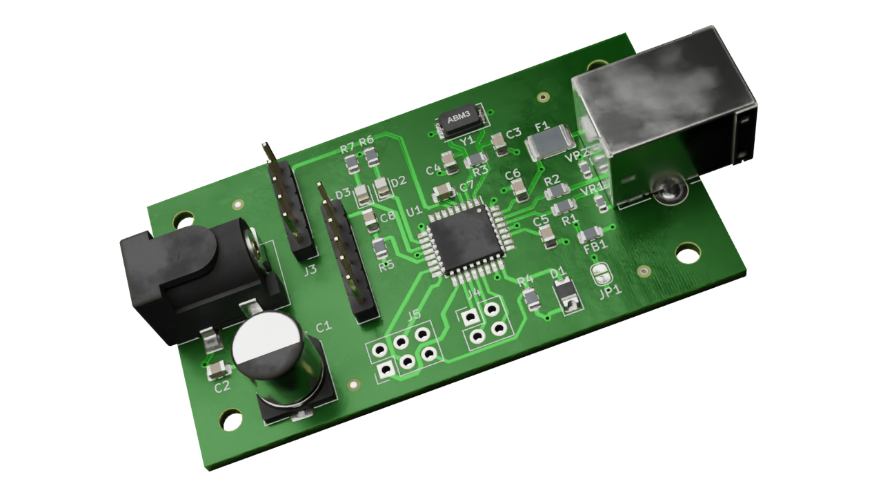
Excluded components are removed from the 3D model (STEP file, 3D Viewer render and Blender export):
- Default variant (click to enlarge)

- XTAL variant (click to enlarge)
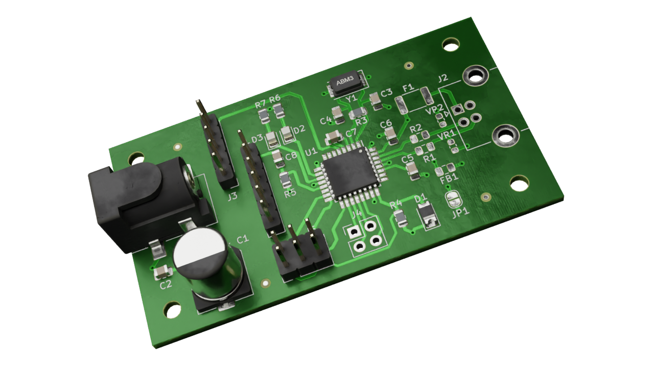
- USB variant (click to enlarge)
Variants can also affect any of the component fields. In order to overwrite one field value when a variant is selected you must define a field named VARIANT:FIELD.
The value for this field will replace the value of the regular FIELD when the VARIANT is in use.
Here is an example, if you have a resistor with a value of 1k and you want this value to change to 2k2 when the test variant is in use you just need to define a field named test:value and assign 2k2 to this field.
To enable it you just need to add a pre_transform filter of the type var_rename to the variant performing the transformation. Suppose you have the following variants:
variants:
  - name: 'production'
    comment: 'Production variant'
    type: kibom
    file_id: '_(PROD)'
    variant: PROD

  - name: 'development'
    comment: 'Development variant'
    type: kibom
    file_id: '_(DEV)'
    variant: DEV
And you want to both apply such a transformation you can define:
filters:
  - name: 'Variant rename'
    type: var_rename
    separator: ':'
    variant_to_value: true

variants:
  - name: 'production'
    comment: 'Production variant'
    type: kibom
    file_id: '_(PROD)'
    variant: PROD
    pre_transform: 'Variant rename'

  - name: 'development'
    comment: 'Development variant'
    type: kibom
    file_id: '_(DEV)'
    variant: DEV
    pre_transform: 'Variant rename'
The separator option controls which character is used to separate the VARIANT and the FIELD in the field name.
The variant_to_value enables the conversion from fields named VARIANT to the component value when the variant is in use.
To make things simpler you can use an internally defined filter called _var_rename. This is a var_rename filter with : as separator and variant_to_value disabled. Using it the configuration is simpler:
variants:
  - name: 'production'
    comment: 'Production variant'
    type: kibom
    file_id: '_(PROD)'
    variant: PROD
    pre_transform: '_var_rename'

  - name: 'development'
    comment: 'Development variant'
    type: kibom
    file_id: '_(DEV)'
    variant: DEV
pre_transform: '_var_rename'The configuration file used in this example can be found here.