RiceTimer (previously known as "ShiftWatch") is a portable standalone data logger intended for collecting and analyzing automotive performance data in real time. Its core function is to stream synchronized raw GNSS + IMU + CAN data to a MicroSD card.
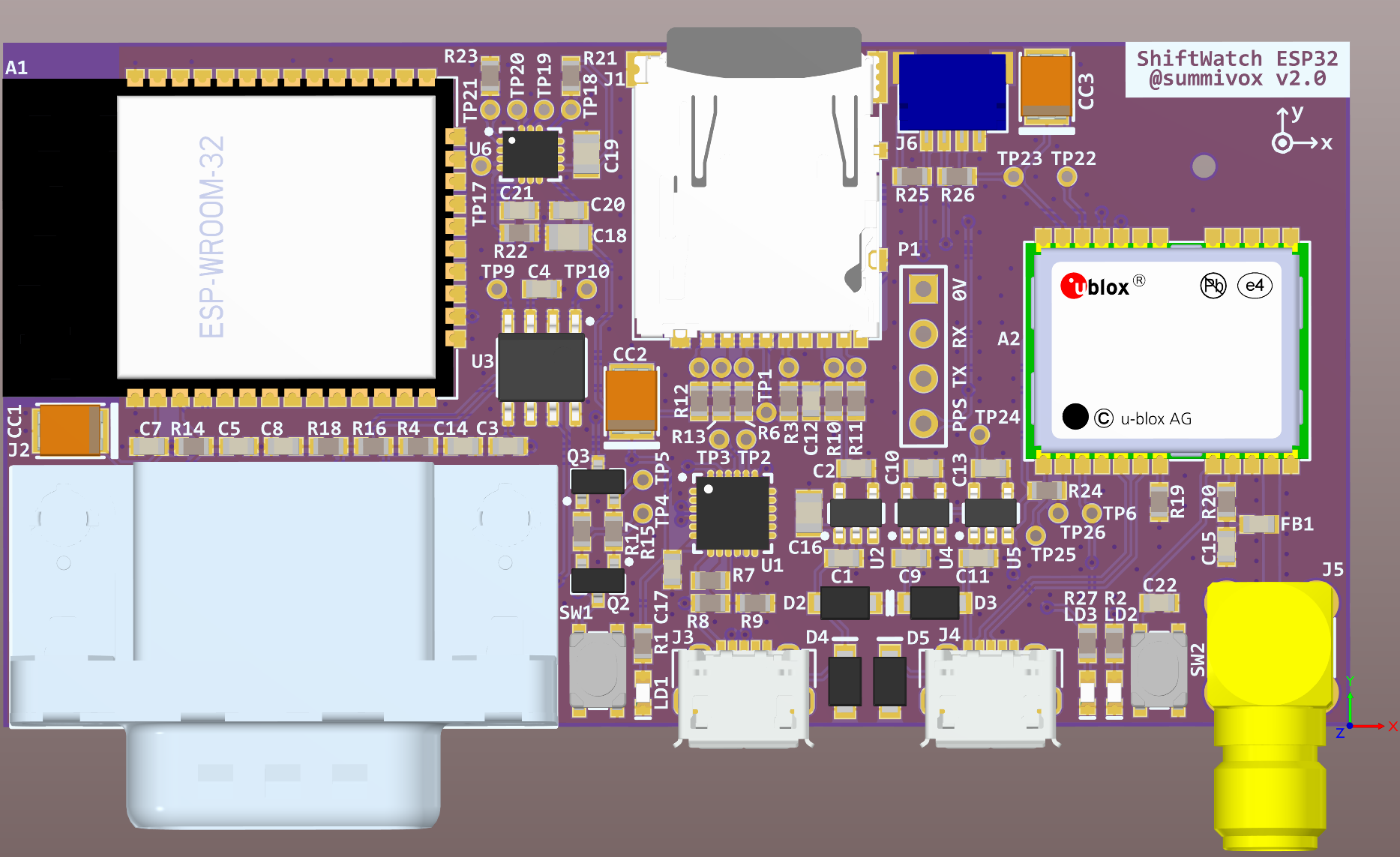
Photo of the current prototype hardware:
Hardware:
- Based on the ESP32 (classic) WROOM module with Wi-Fi/BLE connectivity.
- Flexible power input: USB or 5 ~ 14 V direct input.
- High-contrast monochrome OLED display (128x64).
- Onboard push buttons and a clickable rotary encoder for user interaction.
Logging:
- Human-readable text-based raw log format
- One line per data point.
- Each valid NMEA sentence from the GNSS module is written verbatim to the log.
- Every message is timestamped w.r.t. the GNSS UTC clock:
- Each IMU reading is timestamped by hardware, at the time of data available.
- Each incoming CAN message is timestamped by firmware, at the time of message delivery.
- uBlox NEO series GNSS receiver module + external active antenna (thru the onboard SMA connector)
- ST LSM6 series (LGA14) 6-axis IMU (accelerometer + gyroscope)
- One 3.3V non-isolated CAN transceiver channel:
- Compatible with 5V networks
- 11/29 bit frames (FD not supported)
Short side:
-
USB Micro-B Jack: Supplies power to the device, and serves as the serial debugging/programming console of the ESP32 (CP210x-based).
-
JST SH 5-pin Jack: Combined CAN + Power Input port, intended for a direct automotive connection.
- Pin 1: GND
- Pin 2: VIN (5 ~ 14 V nominal)
- Pin 3: Reserved
- Pin 4: CAN L
- Pin 5: CAN H
-
SMA Jack: External active antenna connection for the GNSS module (required because there is no built-in GNSS antenna). Examples: SparkFun, Adafruit.
Long side:
-
JST SH 4-pin Jack: I2C port in the QWIIC / StemmaQT standard.
- Pin 1: GND
- Pin 2: VCC (3.3 V nominal)
- Pin 3: SDA
- Pin 4: SCL
-
Micro SD Card Slot: While any Micro-SDHC card can work as long as there's not much incoming CAN data, a low-latency one is recommended to avoid any potential data loss under heavy traffic. Usually these cards are branded as "Industrial", "Endurance", "for Dashcam", etc.
(TBD)
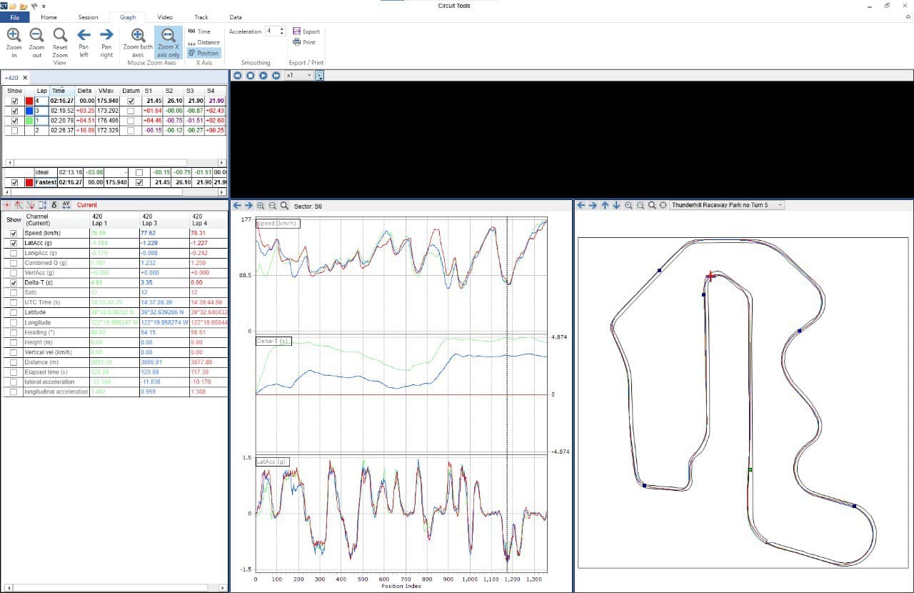
Data captured at Thunderhill East Racetrack (using earlier prototype hardware + firmware) was post-processed and converted to a space-separated table format accepted by external tooling for further analysis:
See this file. Note that GPS coordinates are partially redacted for privacy; as a result the checksums will not match.
The firmware is built through ESP-IDF, preferrably using the official VSCode environment/plugin.
More details on the (previous) prototype PCB platform:
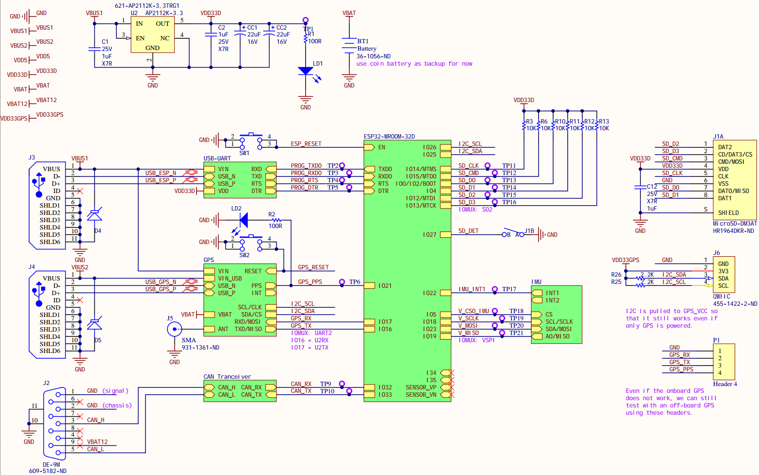
While ESP32 has flexible GPIO routing, the following components are fixed in order to take advantage of fast "IOMux" pins:
- 4-bit SD card bus
- SPI bus for the IMU
- UART for the GPS receiver (optional)
The board is extensible through the 4-pin I2C header in the QWIIC/StemmaQT standard. Currently this is used to connect a 128x64 OLED screen (SH1107 controller), such as this one from Adafruit].
Also, the native USB-serial port of the uBlox NEO has its own USB Micro-B connector, which is designed to power only the GPS module, in isolation from the rest of the board.
- Stabilize log format and post-processing. Right now the log file format has not been formally specified, although considering the deliberately limited feature set of this device, this should be relatively straightforward as the hardware platform also stabilizes.
- Sensor Fusion and Calibration. The goal is to fuse GNSS and IMU signals together, resulting in a higher accuracy vehicle pose signal (e.g. of the vehicle's rear-axle center frame). This requires calibration of rigid transformations among {IMU, Vehicle, GNSS Antenna}.
- Predictive Lap Timer. Currently we only show some basic real-time info on the attached I2C OLED screen for diagnostics (mostly making sure the device is still functional). The goal is to also perform predictive lap timing.
- DBC-based CAN bus parsing. DBC files are an industry standard for defining signals broadcast on a CAN bus. See the OpenDBC project for examples. Loading a DBC file onto the device will allow us to extract and utilize real-time signals from the CAN bus, e.g. engine RPM, fluid temperatures, vehicle's own IMU, wheel speeds, etc. Note that this will explicitly not affect logging output --- log will always contain raw CAN messages.
- Enable WiFi/BLE connectivity. The choice of ESP32 as the main processor is exactly so that we could do this after the core functionality is done.
- Enclosure Design. So that I don't have to velcro the naked PCB down to my car's center console anymore...
This project is currently not ready to accept contributions.


