There are various alternatives when interfacing with LEGO Mindstorms. But there are two easy ways for get going as I understood. Either Matlab Simulink or LEGO Mindstorms SDK. Each of them has their own drawback and limitations.
-
Matlab Linux version up to 17b does not support Bluetooth. Then communicate robot we have to use either USB or wifi. To use wifi, wifi adapter is required.
-
In order to do real-time monitoring, there is only one communication method (wifi) is supported by Matlab Simulink with LEGO Mindstorms hardware. Which mean when using USB or Bluetooth, real-time monitoring is not possible.
- It does not support Linux yet.
After playing around those death ended problems I have decided to use LEGO Mindstorms SDK in windows.
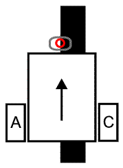
In line following robot, the basic goal is to move robot such that it won't move away from the path is being followed. If it moves away, need to bring it back to the path in an optimal manner. To achieve this goal, PID controller can be employed to reduce the overall error.
Let’s define the problem statement. Idea is to follow the line. So try to track the edge of the path and reduce overall error in real time. Since the color sensor is used to detect line, let’s say for black it returns 50 and for white, it returns 40. To find out midpoint where colour sensor should be pointed, below equation can be used.
midpoint = black + (black-white)/2
The error can be defined as
error = midpoint - color sensor reading value
If the color sensor reading value is 40, then an error will equal to 15 (55-40). To reduce this error we can do multiplying error term with some constant (Kp). This gives how much robots should move another side to reduce the error. In this case Kp = 1, and it should be around 1 to reduce error. If it high error getting high and higher and no way to reduce it. Since we have two colours, in other words, two values (40 and 50), what happens when robot went away from the path. It keeps getting a constant error. So how do we address this problem? We need to sum up previous errors and reduce it to get the robot back to the path. Let’s take robot moving away from the path. Then when we are adding all those previous errors it will get bigger and bigger. To reduce it, we have to overshoot robot other direction much as possible. This also experiences robot oscillation. To avoid getting a bigger integral error, we can multiply integral error by some constant (Ki) to reduce it. Up to now, we are able to reduce the current error (Kp) and the previous error (Ki). To reduce error which can happen in the future, we have thought a little bit more. Let’s put it on this way, the next error is expected to be the current error plus the change in the error between the two preceding sensor samples. The change in the error between two consecutive points is called the derivative. The derivative is the same as the slope of a line. So this is the solution for reducing an error which will happen in the future. Like previously, to control this error we can multiply some constant (Kd). In PID controller, basic idea is that and need to find proper value for Kp, Kd and Ki. Then, the robot can move along the line very smoothly.
This is nothing but need to find a value for black and white space. This can be done in Matlab or using LEGO Mindstorms SDK,
This is the LEGO Mindstorms configuration to read the colour sensor values. In this, I have added an additional sensor (touch) for the convenience. First, reads black or white and when it press again it reads again. In here, it should read white and then black.


Pseudo code for PID controller
            program LINE FOLLOWING
              white = 0, black = 0
              CALIBRATE()
              midpoint = ( white - black ) / 2 + black
              kp = 1, ki = 1, kd = 1
              lasterror=0
              repeat
                value = Read Light Sensor
                error = midpoint - value
                integral = error + integral
                derivative = error - lasterror
                correction = kp * error + ki * integral + kd * derivative
                Turn B+C Motors by correction
                lasterror = error
              done repeat
            done program
To turn Kp, Ki and Kd values, I have set Ki and Kd values to zero and put Kp to 1. Reason for putting it into 1 I explained above under section: Requirement of PID Controller. Then try to see the system and change it up when system keeps oscillating. Then Ki is increased until the response time or transient process time get reduced up to a considerable level. To decide where to stop I have used if a system having high overshoot which means it reached where it can not be increased any more. So then I set Kd to 1 and check it converges to stable state very fast. If it does not try to reduce by a factor of 2 and finally was able to find proper values for Kp, Ki and Kd which I think the optimal values for this robot in this environment. Because by changing those coefficients I was able to increase the rise time, eliminate the steady-state error, control and improve the overshoot of robot.
LEGO Mindstorms file for PID controller can be found here: https://github.com/GPrathap/LineFollowingRobot/blob/master/LineFollowingRobot.ev3
LineFollowingRobot.ev3 script you can change Kp, Ki and Kd coefficients. In this script Kp, Ki and Kd are denoted as a,b and c respectively. My final calibration those coefficients were a=0.8, b=2.6 and c=8.8.
Result in action: https://www.youtube.com/watch?time_continue=1&v=3Iw4T13xOgU
