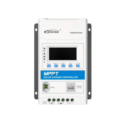
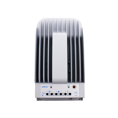
An Arduino project to connect the EPSolar/EPEver Tracer A/B, Xtra, Triton Series MPPT Solar Controllers (RS-485 Modbus) to an ESP8266 and monitor it using the Blynk mobile app, the reloaded version!
This is almost complete rewrite of the original project, with ton of improvements, refactored code, brand new Blynk project, and wider compatibility of RS485 convertrs.
Feel free to make pull requests if you wish to help improving. There is also a support forum on the Blynk community forums: https://community.blynk.cc/t/epsolar-tracer-2210a-charge-controller-blynk-epic-solar-monitor/10596
-
RS485 UART Module (
not the MAX485 chip!-@tekk:I'm using MAX485 cheapo module and it works fine!) -
An old ethernet cable with RJ45 connector you are happy to cut open
Cut open your ethernet cable and split out pin 3, 5, 7 (B, A, GND). Refer to Tracer Modbus PDF for additional info.
Follow the wiring guide below: (note that the 2-pol switch is only needed during flashing) No longer needed!
Note: as @Don Vukovic noted, there is probably reversed RX and TX on this schematic. Correct is: DI to TX, and RO to RX
Follow links to get them.
Firstly, enter WiFi credentials in esp_credentials.h.
You will be able to use this file by including it in any sketch by entering #include <esp_credentials.h>. (This include is already present in settings.h, there's no need to add it.)
Example:
/**************************************************************
 *           Settings - Wifi Credentials
 **************************************************************/
#define WIFI_SSID             "xxxxxxxxxxxxxxxxxxxxxxxxxxxxxxxx"
#define WIFI_PASS             "xxxxxxxxxxxxxxxxxxxxxxxxxxxxxxxx"
- Open the Blynk mobile app and create a new project by scanning the following QR code
- Send yourself the generated auth code
- Paste your auth code into
esp_credentials.h:
#define AUTH "xxxxxxxxxxxxxxxxxxxxxxxxxxxxxxxx"Disconnect TX/RX cables (or open the switch if you have one)- You don't have to do this anymore! But it's always best to have it disconnected.
- Upload the sketch to your ESP8266
Once uploaded, reconnect the TX/RX cables and plug the cable in to the Tracer COM port- Just plug the ethernet cable to the Solar controller. Anyhow, it is always a good idea to repower the MAX485 module, if you're using one, between sketch uploads
- Load the Blynk project and hit PLAY button to start receiving data
-
MAX485 module:
I'm using this cheapo module and it works quite fine.
It's powered from +5V from ESP8266, and wired as following:
-
MAX485 module <-> ESP8266
DI->D10/GPIO1/TXRO->D9/GPIO3/RXDEandREare interconnected with a jumper and then connected do eighter pinD1orD2VCCto+5V/VINon ESP8266
-
Tracer A/B MPPT Controller Ethernet cable <-> MAX485
- Ethernet green, pin
5->A - Ethernet blue, pin
3->B - Ethernet brown, pin
7->GNDon module and ESP8266GNDpin- -> to prevent ground loops - important!
- Ethernet green, pin
I plan to add more features and pull more data from the controller once I have my own solar system running. If you'd like to pick this up and have a go at adding features, I'll be happy to accept pull requests.
You are welcome for suggestions, bugreports, and of course any further improvements of this code.
- Rewrote whole sketch
- Tried to utilize HardwareSerial
UART2- no avail :(ModbusMasterlibrary is incopatible withSoftwareSerial, (don't even try)... Would need to rewrite wholeModbusMaster, so Hardware UART is the only option for smooth & seamless communication because of the interrupt driven data transmission, more precise timing, and HW buffer, and stuff
- Optimized for very cheap MAX485 module, you can buy it from usual sources...
- Feature: Added option to switch the output of the Tracer MPPT Controller ON/OFF from the Blynk app
- Improvement: You no longer need to disconnect and reconnect Modbus RS485 Serial port from the ESP8266 while uploading
- Code rewrote to use as little magic constants as possible
- Added
preTransmissionabdpostTransmissionModbus handling / signalling, just to be sure... - Added calls to
ESP.wdtDisable()andESP.wdtEnable(1), temporary System Watchdog shutdown and later found it to be not necessarry- Avoids unwanted rebooting of ESP8366 while receiving data from the Modbus
- Added more debug outputs and results to USB Serial


