| First Print | Completed Panels |
|---|---|
 |
 |
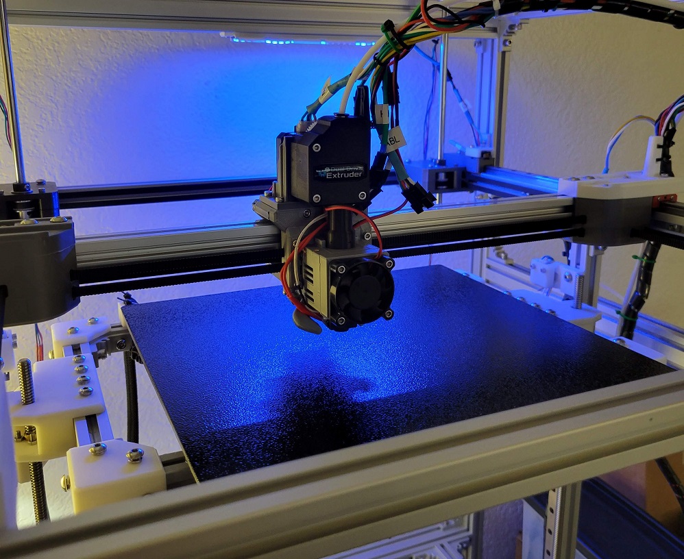
This is the evolution of the concept of a fully enclosed, temperature-controlled 3D printer with externally mounted steppers motors. The idea of building an enclosed 3D printer to suit my specific needs came during the 2021 Winter Storm. Clock 1 was a thought experiment to enclose an Ender 5-like Cartesian printer. Clock 2 was a from-scratch CoreXY printer that I largely built before acquiring the ability to safely print ABS.
Clock 3 is a complete redesign incorporating most of the common, off-the-shelf components from Clock 2. It incorporates lessons from repeated assembly/disassembly of Clock 2, successful concepts from other projects, and a lot of experimentation with ABS in an enclosure. Clock 3 is a working name for this project and is not final.
The core Fusion 360 files are pretty trashed due to interdependancies. I've had to halt development for now.
Documentation of the initial prootype is ongoing and active. The most recent compiled markdown can be viewed at jon-harper.github.io/clock-3/. Follow-on releases will address minor issues discovered in the process that do not require immediate resolution.
- Klipper firmware for Clock 3 is available here.
- The Clock Face project is here, which revises the physical display and menu system for Klipper.
- The Fusion 360 model is not published yet, but you can find the project's Python scripts here
- This project is very much under active development, first printing on 12/21/2021.
- Head to the Media folder for renders and photos of the prototype.
STLs are numbered sequentially to help with assembly. The number of each component is printed discreetly on each piece so that it is either concealed or very hard to see after installation. Each component falls into one of several categories and is identified by either its name or location. Components that come in left and right versions have chirality.
The printed text on each component also include an L or R for chiral components to help with identification. Some miscellanious and very basic parts lack numbers due to size or geometry constraints.
Example: 01 - XY - Pulleys - L Bottom.stl
You can find all of the printable files in the STL folder along with a list of part codes.
What one board labels as "THB" another may label as "TB". Likewise, endstop/limit switch connector abbreviations (and pin order!) are not standard, inasmuch as anything in 3D printing is standardized. To that end, a single nomenclature is adopted for part labels. Each connector has a two- or three-letter code for labeling panels and wiring. Your actual wiring may use a different system, but printed parts with labels follow this pattern. It is recommended for continuity with printed parts and documentation to use the same. The full part list may be found in the Docs folder.
There are a number of tools to help determine parametric details such as the ideal M5 screw hole size or the proper hole size for your brand of brass inserts. These can be found in the STL/Tools folder and are meant to be printed. The results can be fed back in to the Fusion model and then exported for printing. Stock exported STL files will come with default tolerances and may not fit as precisely.
There is also a CAD/Tools folder with parametric tools such as an LED channel.