-
Name : LCR_meter
-
Title : Inductance, Capacitance and Resistance meter, Arduino NANO based.
-
Description :
- Inductance, Capacitance and Resistance meter.
- Arduino NANO version 3.0 based.
- 4 resistor test ranges, Resistor range is from 0 ohms to 2 Mohms. Auto-range.
- Inductance test, range is 80uH to 30,000uH.
- Capacitance three tests , range 18pf to 4F.
- Push button input.
- Outputs data to serial monitor and a HD44780 LCD 16x02 I2C.
-
Platform: Arduino NANO version 3.0
-
Author: Gavin Lyons
- Overview
- Table of contents
- Parts List
- Project Schematic
- Control
- Example Output
- C Meter
- R Meter
- L Meter
- Libraries
The BOM is available in documentation folder in file LCR_meter_bom.txt
Pin and test socket connection data are available in documentation folder in file PinoutConnectionsTables.md
- Pinout Connections Tables
- Tesk Socket layout
Push Buttons
- Mode Button to change mode.
- Test button to start test for selected mode, when in ready mode this button brings up help screen.
Tests Modes:
- Inductance test.
- 0 to 2k range resistor test.
- 2K to 20k range resistor test.
- 20k to 200k range resistor test.
- 200k to 1M range resistor test.
- Capacitor Test 1 Range 1 uF to 4F.
- Capacitor Test 2 Range 18 pF to 470 uF.
- Capacitor Test 3 Range 4.7 nF to 180 uF.
The meter outputs to an LCD and serial monitor. (The LCD is optional as data is sent via serial monitor to PC) Every point in code that requires User calibration on Initial build is marked "USER CALIBRATE"
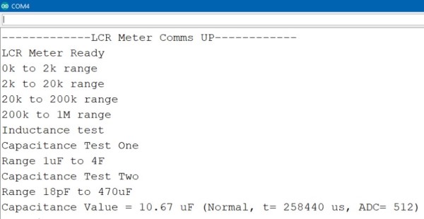
Example output for Capacitor test 2 on a 10uF capacitor to LCD and serial monitor.
Each Arduino capacitance test relies on a property of resistor capacitor (RC) circuits- the time constant. The time constant of an RC circuit is defined as the time it takes for the voltage across the capacitor to reach 63.2% of its voltage when fully charged:
Larger capacitors take longer to charge, and therefore will create larger time constants. The capacitance in an RC circuit is related to the time constant by the equation:
The capacitance meter has an RC circuit with known resistor values and an unknown capacitor value. The Arduino will measure the voltage at the capacitor and record the time it takes to reach 63.2% of it’s voltage when fully charged (the time constant). Since the resistance value is already known, we can use the formula above in a program that will calculate the unknown capacitance.
Test 1
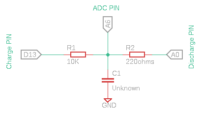
Test 1: Range 1 uF to 4F. Uses two digital pins, one analog pin, and two resistors. One for discharge, one for charge. Insert a capacitor in range into terminal press button and view result on LCD or serial monitor. The Capacitor is charged, We can measure elapsed time until time constant fulfilled using analog pin and we know R value. Therefore we solve for C. The result gives two values: Capacitance value and time constant to test in mS. The user can adjust the 10K resistor value in code variable(resistorValue) to match exact value, to improve accuracy.
Test 2
Test 2 : Range 18 pF to 470 uF.
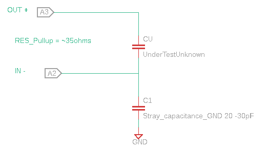
This capacitance test has the greatest range of 3. It also had the highest accuracy with smaller capacitors. No resistors are needed and it only uses two analog pins(A2(neg) and A3(positive) from the Arduino. There is no extra resistor just the internal components of ATmega328 chip.
C1 calibration(optional):
The internal analog pin capacitor to gnd (C1) varies between 20 and 30pF. unknown capacitor = Cu. The positive pin is set to 5V, the negative to 0V.
VA2 = (VA3 * Cu)/(C1 + Cu)
The value of C1 for any given Arduino board will have to be calibrated using a known cap for Cu, for full accuracy I set it at 24.48pF in code (CapOne) Found using equation.
C1 = Cu * (VA3-VA2) / VA2
Where Va2 is ADC value reported by code and VA3 is 5v or 1023. So for a known capacitor of 103pF giving a ADC value of 801.
C1 = 103pf * (1023-801)/ 801 = 28.48pF.
The user should change this for their system to improve accuracy. Test a known cap get ADC value and then pop these values into equation above and put the C1 value into (CapOne) variable in code.
Test equation:
Cu = VA2 * C1 / (VA3 - VA2)
The test displays 3 values
- Cu, Capacitance in Farads
- Time constant for test in mS
- Va2 , ADC measurement from 0 to 1023 where 1023 is 5V
Test 3
Test 3 Range 0.0047 uF to 180 uF.
A voltage divider is created to give a reference voltage,
Vout = Vin * (R5 / (R5 + R4)) , 5 * (3100 / (1800 + 3100)) = 3.163.
The objective here is to find the time constant τ (tau) in the equation:
τ = R * C Solved for C: C = τ / R
So we want to charge the capacitor under test with a suitable voltage (eg. 5V from an Arduino output pin) and measure how long it takes to reach 63.2% of that voltage. So we need a reference voltage of 5 * 0.632, namely 3.16V. The internal analogue comparator is used for this job.:
- pin 6 PD6 AIN0
- pin 7 PD7 AIN1
We connect the reference voltage to the AIN1 pin (negative reference) and connect our capacitor to the AIN0 pin (positive reference) and then configure an interrupt on the rising edge. A value of 10K for the resistor to give a reasonably slow charge time. The value of ~ 10K is specified in code variable (resistance). so adjust for your resistor value. Make sure to pick accurate resistors for voltage divider.
The test returns the Capacitance result and time constant.
The resistors used in circuit should be measured on good quality meter and there exact values added to code for maximum accuracy. This Resistance test can auto-range in both directions.
0-2kohms : 2kohms resistor
2k-20k : 20k resistor
20k-200k : 200k resistor
200k - 1Mohm : 1 Mohm resistor
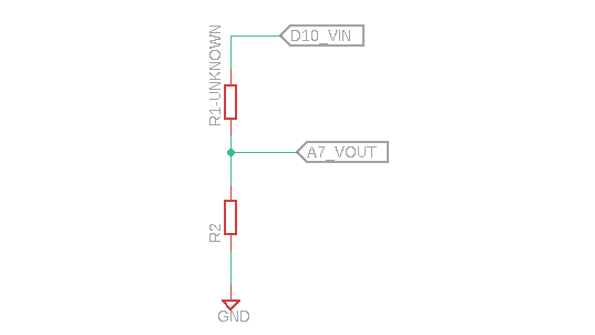
So we will use a basic voltage divider to calculate the resistance.
A voltage divider is made of two Resistances (R1 and R2) in series. The output voltage in the middle point is [R2/(R1+R2)]Vin. Using this formula and knowing the value of R2 and measuring the Vout calculate the resistance of R1. Vin will be 5 volts from the Arduino, We can measure Vout with one of the Arduino's analog inputs. We need to use different ranges of R2 to measure with better precision.
This tests range is from 80uH to 30,000uH. Ideally the capacitors in circuit must be in specification and measured on a good quality meter. The unknown test inductor is placed in parallel with a capacitor thus creating an LC circuit.
As soon as the voltage on the LC circuit becomes positive, the LM393 will be floating, which can be pulled high with a pull up resistor. When the voltage on the LC circuit becomes negative, the LM393 will pull its output to ground.
A 5V pulse signal from Arduino is applied to the LC circuit. We charge the circuit for some time. Then we change the voltage from 5 volts directly to 0. That pulse will make the circuit resonate creating a sinusoidal signal oscillating at the resonant frequency. The frequency is measured and later using the formulas we can obtain the inductance value. We will use the Arduino to measure the frequency and calculate the value. The resonant frequency is measured with the next equation:
So we could obtain the L value because we know the F frequency that we've just measured and we also know the value of the capacitor because it's a component that we've selected. All we need is to obtain L from this equation.
The comparator will turn the sine wave into a square wave with a duty of 50%(see fig 9 in datasheet), The microcontroller measures the signal , This measurement can then be doubled to get the period and the inverse of the period is the frequency. Since the circuit is resonating, this frequency is the resonating frequency.
We can now solve the equation for inductance.
-
For the LCD , HD44780_LCD_PCF8574 V1.3.0 , also written by Author.
-
Simple Push button library included in code folder v1.0.0.


