JP6461381B2 - 回転電機の固定子、回転電機、および、回転電機の固定子の製造方法 - Google Patents
回転電機の固定子、回転電機、および、回転電機の固定子の製造方法 Download PDFInfo
- Publication number
- JP6461381B2 JP6461381B2 JP2017567980A JP2017567980A JP6461381B2 JP 6461381 B2 JP6461381 B2 JP 6461381B2 JP 2017567980 A JP2017567980 A JP 2017567980A JP 2017567980 A JP2017567980 A JP 2017567980A JP 6461381 B2 JP6461381 B2 JP 6461381B2
- Authority
- JP
- Japan
- Prior art keywords
- iron core
- stator
- fitting
- rotating electrical
- electrical machine
- Prior art date
- Legal status (The legal status is an assumption and is not a legal conclusion. Google has not performed a legal analysis and makes no representation as to the accuracy of the status listed.)
- Active
Links
- 238000004519 manufacturing process Methods 0.000 title claims description 30
- XEEYBQQBJWHFJM-UHFFFAOYSA-N Iron Chemical group [Fe] XEEYBQQBJWHFJM-UHFFFAOYSA-N 0.000 claims description 199
- 238000000034 method Methods 0.000 claims description 12
- 239000000463 material Substances 0.000 claims description 3
- 230000002093 peripheral effect Effects 0.000 claims description 3
- 238000004080 punching Methods 0.000 claims description 2
- 238000003780 insertion Methods 0.000 description 9
- 230000037431 insertion Effects 0.000 description 9
- 238000004804 winding Methods 0.000 description 8
- 230000000694 effects Effects 0.000 description 5
- 229910000831 Steel Inorganic materials 0.000 description 2
- 230000001154 acute effect Effects 0.000 description 2
- 230000015572 biosynthetic process Effects 0.000 description 2
- 239000004020 conductor Substances 0.000 description 2
- 239000010959 steel Substances 0.000 description 2
- 239000011248 coating agent Substances 0.000 description 1
- 238000000576 coating method Methods 0.000 description 1
- 230000004907 flux Effects 0.000 description 1
- 239000012212 insulator Substances 0.000 description 1
- 230000002452 interceptive effect Effects 0.000 description 1
- 230000011218 segmentation Effects 0.000 description 1
Images
Classifications
-
- H—ELECTRICITY
- H02—GENERATION; CONVERSION OR DISTRIBUTION OF ELECTRIC POWER
- H02K—DYNAMO-ELECTRIC MACHINES
- H02K1/00—Details of the magnetic circuit
- H02K1/06—Details of the magnetic circuit characterised by the shape, form or construction
- H02K1/12—Stationary parts of the magnetic circuit
- H02K1/14—Stator cores with salient poles
- H02K1/146—Stator cores with salient poles consisting of a generally annular yoke with salient poles
- H02K1/148—Sectional cores
-
- H—ELECTRICITY
- H02—GENERATION; CONVERSION OR DISTRIBUTION OF ELECTRIC POWER
- H02K—DYNAMO-ELECTRIC MACHINES
- H02K1/00—Details of the magnetic circuit
- H02K1/06—Details of the magnetic circuit characterised by the shape, form or construction
- H02K1/12—Stationary parts of the magnetic circuit
- H02K1/18—Means for mounting or fastening magnetic stationary parts on to, or to, the stator structures
-
- H—ELECTRICITY
- H02—GENERATION; CONVERSION OR DISTRIBUTION OF ELECTRIC POWER
- H02K—DYNAMO-ELECTRIC MACHINES
- H02K15/00—Methods or apparatus specially adapted for manufacturing, assembling, maintaining or repairing of dynamo-electric machines
- H02K15/02—Methods or apparatus specially adapted for manufacturing, assembling, maintaining or repairing of dynamo-electric machines of stator or rotor bodies
- H02K15/022—Methods or apparatus specially adapted for manufacturing, assembling, maintaining or repairing of dynamo-electric machines of stator or rotor bodies with salient poles or claw-shaped poles
-
- H—ELECTRICITY
- H02—GENERATION; CONVERSION OR DISTRIBUTION OF ELECTRIC POWER
- H02K—DYNAMO-ELECTRIC MACHINES
- H02K15/00—Methods or apparatus specially adapted for manufacturing, assembling, maintaining or repairing of dynamo-electric machines
- H02K15/08—Forming windings by laying conductors into or around core parts
- H02K15/095—Forming windings by laying conductors into or around core parts by laying conductors around salient poles
-
- H—ELECTRICITY
- H02—GENERATION; CONVERSION OR DISTRIBUTION OF ELECTRIC POWER
- H02K—DYNAMO-ELECTRIC MACHINES
- H02K3/00—Details of windings
- H02K3/04—Windings characterised by the conductor shape, form or construction, e.g. with bar conductors
- H02K3/18—Windings for salient poles
-
- H—ELECTRICITY
- H02—GENERATION; CONVERSION OR DISTRIBUTION OF ELECTRIC POWER
- H02K—DYNAMO-ELECTRIC MACHINES
- H02K3/00—Details of windings
- H02K3/32—Windings characterised by the shape, form or construction of the insulation
- H02K3/325—Windings characterised by the shape, form or construction of the insulation for windings on salient poles, such as claw-shaped poles
-
- H—ELECTRICITY
- H02—GENERATION; CONVERSION OR DISTRIBUTION OF ELECTRIC POWER
- H02K—DYNAMO-ELECTRIC MACHINES
- H02K3/00—Details of windings
- H02K3/46—Fastening of windings on the stator or rotor structure
- H02K3/52—Fastening salient pole windings or connections thereto
- H02K3/521—Fastening salient pole windings or connections thereto applicable to stators only
- H02K3/522—Fastening salient pole windings or connections thereto applicable to stators only for generally annular cores with salient poles
-
- H—ELECTRICITY
- H02—GENERATION; CONVERSION OR DISTRIBUTION OF ELECTRIC POWER
- H02K—DYNAMO-ELECTRIC MACHINES
- H02K2203/00—Specific aspects not provided for in the other groups of this subclass relating to the windings
- H02K2203/12—Machines characterised by the bobbins for supporting the windings
Landscapes
- Engineering & Computer Science (AREA)
- Power Engineering (AREA)
- Manufacturing & Machinery (AREA)
- Iron Core Of Rotating Electric Machines (AREA)
- Manufacture Of Motors, Generators (AREA)
Description
鉄心には、環状に形成されるヨーク部と、
前記ヨーク部の内周側に周方向に間隔を隔てるとともに前記ヨーク部に対して径方向の内側に突出して形成される複数のティース部と、
隣接する前記ティース部の径方向の内側同士を連結する連結部とを有し、
各前記ティース部の間に形成されたスロットに設置されるコイルを備えた回転電機の固定子において、
前記鉄心は、前記ヨーク部を構成する外側鉄心と、
前記ティース部および前記連結部を構成する内側鉄心とにて形成され、
前記外側鉄心は、周方向において複数に分割して形成され、
複数に分割された前記外側鉄心のそれぞれと、複数の前記ティース部とには互いに嵌合するための第一嵌合部が複数形成され、
当該複数の前記第一嵌合部における径方向に添った軸方向に形成される前記外側鉄心および前記内側鉄心の嵌合面の全ては、
分割された前記外側鉄心の周方向における中心位置の径方向に添った軸方向に形成された面と平行な面にて形成される。
上記に示した固定子と、
前記固定子に対して同心円状に配置される回転子とを備えた回転電機。
上記に示した回転電機の固定子の製造方法において、
前記内側鉄心の各前記スロットに前記コイルを設置する第一工程と、
前記内側鉄心の径方向の外側から分割された前記外側鉄心を挿入して前記第一嵌合部にて前記内側鉄心と前記外側鉄心とを前記嵌合面に対して平行に相対移動させて嵌合する第二工程とを備える。
コイルの損傷を防止するとともに生産性に優れている。
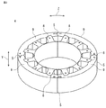
以下、本願発明の実施の形態について説明する。図1はこの発明の実施の形態1における回転電機の構成を示した片縦断面側面図である。図2は図1に示した回転電機の固定子の構成を示す斜視図である。図3は図2に示した固定子の鉄心の構成を示す斜視図である。図4は図3に示した鉄心の内側鉄心の構成を示す斜視図である。図5は図4に示した内側鉄心の構成を示す平面図である。図6は図3に示した鉄心の外側鉄心の構成を示す斜視図である。図7は図6に示した外側鉄心の構成を示す平面図である。
図13はこの発明の実施の形態2における回転電機の固定子の構成を示す斜視図である。図14は図13に示した固定子の鉄心の構成を示す斜視図である。図15は図14に示した鉄心の内側鉄心の構成を示す斜視図である。図16は図15に示した内側鉄心の構成を示す平面図である。図17は図14に示した鉄心の外側鉄心の構成を示す斜視図である。図18は図17に示した外側鉄心の構成を示す平面図である。
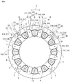
図23はこの発明の実施の形態2における回転電機の固定子の構成を示す平面図である。図24および図25は図23に示した固定子の内側鉄心の製造方法を示す平面図である。図24は内側鉄心を板材から打ち抜いた状態を示す平面図である。図25は図24に示した内側鉄心を丸めて環状に構成した状態を示す平面図である。
Claims (9)
- 鉄心には、環状に形成されるヨーク部と、
前記ヨーク部の内周側に周方向に間隔を隔てるとともに前記ヨーク部に対して径方向の内側に突出して形成される複数のティース部と、
隣接する前記ティース部の径方向の内側同士を連結する連結部とを有し、
各前記ティース部の間に形成されたスロットに設置されるコイルを備えた回転電機の固定子において、
前記鉄心は、前記ヨーク部を構成する外側鉄心と、
前記ティース部および前記連結部を構成する内側鉄心とにて形成され、
前記外側鉄心は、周方向において複数に分割して形成され、
複数に分割された前記外側鉄心のそれぞれと、複数の前記ティース部とには互いに嵌合するための第一嵌合部が複数形成され、
当該複数の前記第一嵌合部における径方向に添った軸方向に形成される前記外側鉄心および前記内側鉄心の嵌合面の全ては、
分割された前記外側鉄心の周方向における中心位置の径方向に添った軸方向に形成された面と平行な面にて形成される回転電機の固定子。 - 前記第一嵌合部は、前記外側鉄心の第一凹部および前記内側鉄心の第一凸部にて形成される請求項1に記載の回転電機の固定子。
- 分割された各前記外側鉄心は、前記外側鉄心の周方向の端部同士に形成された第二嵌合部にて嵌合される請求項1または請求項2に記載の回転電機の固定子。
- 前記外側鉄心の分割箇所は、周方向において前記スロットが形成される箇所に形成される請求項1から請求項3のいずれか1項に記載の回転電機の固定子。
- 前記外側鉄心の分割箇所は、周方向において前記ティース部が形成される箇所に形成され、
前記第一嵌合部は、前記外側鉄心の周方向の端部の箇所に形成される請求項1から請求項3のいずれか1項に記載の回転電機の固定子。 - 前記コイルは、前記ティース部に嵌合するとともに前記ティース部の隣接する両前記スロットに配置されるボビンに巻回され形成される請求項1から請求項5のいずれか1項に記載の回転電機の固定子。
- 請求項1から請求項6のいずれか1項に記載の固定子と、
前記固定子に対して同心円状に配置される回転子とを備えた回転電機。 - 請求項1から請求項6のいずれか1項に記載の回転電機の固定子の製造方法において、
前記内側鉄心の各前記スロットに前記コイルを設置する第一工程と、
前記内側鉄心の径方向の外側から分割された前記外側鉄心を挿入して前記第一嵌合部にて前記内側鉄心と前記外側鉄心とを前記嵌合面に対して平行に相対移動させて嵌合する第二工程とを備えた回転電機の固定子の製造方法。 - 請求項8に記載の回転電機の固定子の製造方法において、
前記第一工程の前に、
上記内側鉄心を板材から直線状に打ち抜いて形成し、前記直線状の上記内側鉄心を丸めて環状に設置する工程を備えた回転電機の固定子の製造方法。
Applications Claiming Priority (3)
| Application Number | Priority Date | Filing Date | Title |
|---|---|---|---|
| JP2016028751 | 2016-02-18 | ||
| JP2016028751 | 2016-02-18 | ||
| PCT/JP2017/000211 WO2017141562A1 (ja) | 2016-02-18 | 2017-01-06 | 回転電機の固定子、回転電機、および、回転電機の固定子の製造方法 |
Publications (2)
| Publication Number | Publication Date |
|---|---|
| JPWO2017141562A1 JPWO2017141562A1 (ja) | 2018-05-31 |
| JP6461381B2 true JP6461381B2 (ja) | 2019-01-30 |
Family
ID=59625818
Family Applications (1)
| Application Number | Title | Priority Date | Filing Date |
|---|---|---|---|
| JP2017567980A Active JP6461381B2 (ja) | 2016-02-18 | 2017-01-06 | 回転電機の固定子、回転電機、および、回転電機の固定子の製造方法 |
Country Status (4)
| Country | Link |
|---|---|
| US (1) | US20180351417A1 (ja) |
| JP (1) | JP6461381B2 (ja) |
| CN (1) | CN108604837A (ja) |
| WO (1) | WO2017141562A1 (ja) |
Families Citing this family (7)
| Publication number | Priority date | Publication date | Assignee | Title |
|---|---|---|---|---|
| JP6785528B2 (ja) * | 2016-10-14 | 2020-11-18 | Nittoku株式会社 | 巻線装置及び巻線方法 |
| CN111478462A (zh) * | 2019-01-24 | 2020-07-31 | 福特全球技术公司 | 用于电机的定子及其制造方法 |
| JP7109658B2 (ja) * | 2019-04-25 | 2022-07-29 | 三菱電機株式会社 | ステータ、モータ、送風機、空気調和装置およびステータの製造方法 |
| DE102020109956A1 (de) | 2020-04-09 | 2021-10-14 | Schaeffler Technologies AG & Co. KG | Zusammenbau eines Stators |
| FR3112905B1 (fr) * | 2020-07-23 | 2023-06-09 | Nidec Psa Emotors | Stator de machine électrique tournante |
| DE102021101911A1 (de) * | 2021-01-28 | 2022-07-28 | Webasto SE | Verfahren und Vorrichtung zum Herstellen eines Stators für einen bürstenloser Gleichstrommotor |
| WO2022218520A1 (de) * | 2021-04-14 | 2022-10-20 | Michael Fick | Stator für eine rotierende elektrische maschine |
Family Cites Families (11)
| Publication number | Priority date | Publication date | Assignee | Title |
|---|---|---|---|---|
| DE19842948A1 (de) * | 1998-09-18 | 2000-03-30 | Siemens Ag | Elektromotor |
| JP2000341889A (ja) * | 1999-05-25 | 2000-12-08 | Hitachi Ltd | 回転機用コア、その製造方法、コア用素片および回転機 |
| US6583530B2 (en) * | 2001-02-20 | 2003-06-24 | Chun-Pu Hsu | Composite stator structure having corresponding concave embedding receiving grooves and arc-shaped teeth surfaces |
| DE10248771A1 (de) * | 2002-10-18 | 2004-04-29 | Siemens Ag | Permanenterregte Synchronmaschine |
| JP3975928B2 (ja) * | 2003-01-31 | 2007-09-12 | 三菱電機株式会社 | 直流モータの電機子構造 |
| JP3987027B2 (ja) * | 2003-03-31 | 2007-10-03 | 三菱電機株式会社 | 回転電機の電機子 |
| DE10361857A1 (de) * | 2003-12-30 | 2005-07-28 | Robert Bosch Gmbh | Verfahren zur Herstellung eines Ständers sowie danach hergestellter Ständer |
| JP2005278238A (ja) * | 2004-03-23 | 2005-10-06 | Ishikawajima Harima Heavy Ind Co Ltd | 電動機のステータコア |
| WO2006114890A1 (ja) * | 2005-04-25 | 2006-11-02 | Mitsubishi Denki Kabushiki Kaisha | アウタロータ型モータのステータ |
| JP4372130B2 (ja) * | 2006-09-08 | 2009-11-25 | 三洋電機株式会社 | モータ |
| DE102007034195A1 (de) * | 2007-07-23 | 2009-01-29 | Robert Bosch Gmbh | Stator in einem Innenläufer-Elektromotor |
-
2017
- 2017-01-06 US US15/770,312 patent/US20180351417A1/en not_active Abandoned
- 2017-01-06 CN CN201780011127.5A patent/CN108604837A/zh active Pending
- 2017-01-06 WO PCT/JP2017/000211 patent/WO2017141562A1/ja active Application Filing
- 2017-01-06 JP JP2017567980A patent/JP6461381B2/ja active Active
Also Published As
| Publication number | Publication date |
|---|---|
| WO2017141562A1 (ja) | 2017-08-24 |
| CN108604837A (zh) | 2018-09-28 |
| US20180351417A1 (en) | 2018-12-06 |
| JPWO2017141562A1 (ja) | 2018-05-31 |
Similar Documents
| Publication | Publication Date | Title |
|---|---|---|
| JP6461381B2 (ja) | 回転電機の固定子、回転電機、および、回転電機の固定子の製造方法 | |
| JP6328319B2 (ja) | 電機子および回転電機 | |
| US10340753B2 (en) | Stator of planar type motor, and planar type motor using same | |
| JP5617313B2 (ja) | 回転電気機械の組み立て方法 | |
| JP5557058B2 (ja) | 回転電機の固定子及びその製造方法 | |
| WO2015159329A1 (ja) | アキシャルエアギャップ型回転電機 | |
| JP5911018B2 (ja) | 電機子およびその電機子を備えた回転電機 | |
| WO2019073724A1 (ja) | 回転電機の固定子 | |
| JP4286829B2 (ja) | 回転機の製造方法 | |
| JP2019088033A (ja) | 電機子 | |
| JP2009177907A (ja) | 回転電動機のステータおよびそれを備えた回転電動機 | |
| JP4002451B2 (ja) | 回転電機 | |
| JP6652308B2 (ja) | 電機子、回転電機および電機子の製造方法 | |
| US20220263356A1 (en) | Motor | |
| JP4386909B2 (ja) | モータ | |
| WO2019146499A1 (ja) | 回転電機の固定子及び回転電機の固定子の製造方法 | |
| JP5256835B2 (ja) | 回転電機の固定子及び回転電機 | |
| JP2007259514A (ja) | 分割形固定子鉄心を採用した回転電機 | |
| JP2017103986A (ja) | 電動機 | |
| JP4574454B2 (ja) | 電動機 | |
| JP2020150753A (ja) | ステータ及びブラシレスモータ | |
| JP7229402B2 (ja) | 電機子の製造方法、及び、電機子 | |
| WO2024176761A1 (ja) | ステータ、及び、それを用いたモータ | |
| JP2019140757A (ja) | 回転電機、回転電機の製造方法、および送風機 | |
| WO2022107713A1 (ja) | モータ及びステータの製造方法 |
Legal Events
| Date | Code | Title | Description |
|---|---|---|---|
| A521 | Request for written amendment filed |
Free format text: JAPANESE INTERMEDIATE CODE: A523 Effective date: 20180207 |
|
| A621 | Written request for application examination |
Free format text: JAPANESE INTERMEDIATE CODE: A621 Effective date: 20180207 |
|
| TRDD | Decision of grant or rejection written | ||
| A01 | Written decision to grant a patent or to grant a registration (utility model) |
Free format text: JAPANESE INTERMEDIATE CODE: A01 Effective date: 20181204 |
|
| A61 | First payment of annual fees (during grant procedure) |
Free format text: JAPANESE INTERMEDIATE CODE: A61 Effective date: 20181225 |
|
| R150 | Certificate of patent or registration of utility model |
Ref document number: 6461381 Country of ref document: JP Free format text: JAPANESE INTERMEDIATE CODE: R150 |
|
| R250 | Receipt of annual fees |
Free format text: JAPANESE INTERMEDIATE CODE: R250 |
|
| R250 | Receipt of annual fees |
Free format text: JAPANESE INTERMEDIATE CODE: R250 |
|
| R250 | Receipt of annual fees |
Free format text: JAPANESE INTERMEDIATE CODE: R250 |


