JP4682589B2 - Piezoelectric actuator and light sweep device using the same - Google Patents
Piezoelectric actuator and light sweep device using the same Download PDFInfo
- Publication number
- JP4682589B2 JP4682589B2 JP2004326187A JP2004326187A JP4682589B2 JP 4682589 B2 JP4682589 B2 JP 4682589B2 JP 2004326187 A JP2004326187 A JP 2004326187A JP 2004326187 A JP2004326187 A JP 2004326187A JP 4682589 B2 JP4682589 B2 JP 4682589B2
- Authority
- JP
- Japan
- Prior art keywords
- arm
- piezoelectric
- mirror
- light beam
- support
- Prior art date
- Legal status (The legal status is an assumption and is not a legal conclusion. Google has not performed a legal analysis and makes no representation as to the accuracy of the status listed.)
- Expired - Fee Related
Links
Images
Landscapes
- Laser Beam Printer (AREA)
- Mechanical Optical Scanning Systems (AREA)
- Micromachines (AREA)
- Facsimile Heads (AREA)
- Facsimile Scanning Arrangements (AREA)
- General Electrical Machinery Utilizing Piezoelectricity, Electrostriction Or Magnetostriction (AREA)
Description
本発明は、圧電駆動型のアクチュエータおよびこれを用いた光線掃引装置に関するものである。 The present invention relates to a piezoelectric drive type actuator and a light beam sweeping device using the same.
従来、レーザープリンタなどに用いられるレーザーから発せられた光線を掃引する光線掃引装置としては、多角形状の回転体の側面にミラーを設けたポリゴンミラーが用いられ、このポリゴンミラーを回転させることにより感光体ドラムの走査面上にレーザー光線を掃引させていた。 Conventionally, as a light beam sweeping device for sweeping light beams emitted from a laser used in a laser printer or the like, a polygon mirror provided with a mirror on the side surface of a polygonal rotating body is used. The laser beam was swept onto the scanning surface of the body drum.
なお、この出願の発明に関する先行技術文献情報としては、例えば、特許文献1が知られている。
そして、近年カラーレーザープリンタの普及やプリンタの小型化に伴い、光線掃引装置の小型化が命題となっている。 In recent years, with the widespread use of color laser printers and miniaturization of printers, miniaturization of light beam sweeping devices has become a proposition.
しかしながら、ポリゴンミラーを用いた光線掃引装置においては、ポリゴンミラーを小型化することに加え、このポリゴンミラーを駆動させる駆動装置が別途必要となるためその小型化が非常に困難なものとなっていた。 However, in the light beam sweeping apparatus using the polygon mirror, in addition to downsizing the polygon mirror, a separate drive device for driving the polygon mirror is required, so that downsizing is very difficult. .
そこで、本発明はこのような問題を解決し光線掃引装置を小型化することを目的とする。 Therefore, the present invention aims to solve such problems and reduce the size of the light beam sweeper.
そして、この目的を達成するために本発明は、光源から発せられた光線を掃引させるアクチュエータを、支持体と、一端がこの支持体に支持された第1のアームと、この第1のアームの他端部に支持されるとともに前記第1のアームの一端から他端に至る延出方向とは逆向きに延出された第2のアームとを備え、これら第1、第2のアームを同一平面に設けるとともに、前記第1のアームに圧電薄膜からなる圧電駆動電極と、前記第2のアームの支持部側に圧電薄膜からなる第2の圧電駆動電極を設け、前記圧電駆動電極の駆動周波数を前記第1のアームの自己共振周波数と前記第2のアームの自己共振周波数との間に設定したものである。 In order to achieve this object, the present invention provides an actuator for sweeping light emitted from a light source, a support, a first arm supported at one end by the support, and the first arm. A second arm supported by the other end and extended in the direction opposite to the extending direction from one end of the first arm to the other end, and the first and second arms are the same. A piezoelectric drive electrode made of a piezoelectric thin film is provided on the first arm, and a second piezoelectric drive electrode made of a piezoelectric thin film is provided on the support side of the second arm, and the drive frequency of the piezoelectric drive electrode is provided. Is set between the self-resonant frequency of the first arm and the self-resonant frequency of the second arm.
このような構成とすることで、光線を掃引させる為のアクチュエータを小型化でき、ひいてはこのアクチュエータを用いた光線掃引装置を小型化できるのである。 By adopting such a configuration, the actuator for sweeping the light beam can be reduced in size, and thus the light beam sweeping device using this actuator can be reduced in size.
以下、本発明の一実施形態について図を用いて説明する。 Hereinafter, an embodiment of the present invention will be described with reference to the drawings.
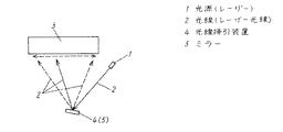
図1はレーザービームプリンタの感光ユニットを模式的に表したものであり、光源となるレーザー1と、このレーザー1から発せられたレーザー光線2が照射される感光ドラム3と、レーザー光線2を反射させるとともにその反射方向を可変させることでレーザー光線2を感光ドラム3の走査面上を掃引させる光線掃引装置4により形成されている。
FIG. 1 schematically shows a photosensitive unit of a laser beam printer. A laser 1 serving as a light source, a photosensitive drum 3 irradiated with a
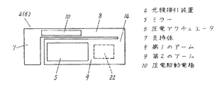
そして、この感光ユニットに用いられる光線掃引装置4におけるミラー5を駆動させる圧電アクチュエータ6は図2に示されるように、基本的にシリコン基板をベースとしたもので、外部取り付け用に設けられた支持体7から一方向に延出された第1のアーム8と、この第1のアーム8の先端部分から支持体7側に向けて延出された第2のアーム9がシリコン基板で一体に形成されており、第1のアーム8の支持体7側の表面に圧電駆動電極10が設けられた構成となっている。
The
また、この圧電駆動電極10の構成は、図3に示されるようにチタン酸ジルコン酸鉛(PZT)により形成された圧電薄膜11を上部電極12と下部電極13により挟み込んだ構成であり、これらの上部電極12、下部電極13および圧電薄膜11は第1のアーム8を形成するシリコン基板上に順次スパッタリングにより形成されるものである。
The
また、図2に示される第2のアーム9の開放端側に設けられているミラー5は金やアルミの層として形成されるもので、この層も圧電駆動電極10と同様にスパッタリングにより形成されるものである。
Further, the
そして、この圧電アクチュエータ6は図3に示される上部電極12と下部電極13との間に駆動電圧を印加することにより圧電駆動電極10が上下方向に撓むため、この撓みにより第1のアーム8及び第2のアーム9が上下方向に撓むことになり、この第2のアーム9の撓みによりその表面に形成されたミラー5の角度が変化することが出来るものである。
In the
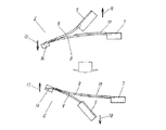
具体的には図4に示されるように、先ず第1のアーム8が圧電駆動電極10により機械的に下方に撓ませた場合、第1のアーム8の先端部分に支持されている第2のアーム9の支持部14が矢印15で示すように下方に移動することになるが、第2のアーム9は先端側の慣性モーメントにより矢印16で示すように上方に撓むこととなる。次に第1のアーム8を圧電駆動電極10により機械的に上方に撓ませた場合、第1のアーム8の先端に支持されている第2のアーム9の支持部14が矢印17で示すように上方に移動することになるが、第2のアーム9は先端側の慣性モーメントにより矢印18で示すように下方に撓むこととなる。
Specifically, as shown in FIG. 4, when the first arm 8 is first mechanically bent downward by the
この構成によれば、ミラー5の傾斜角の可変幅が第1のアーム8の撓み角と第2のアーム9の撓み角との合成により形成されるため、圧電アクチュエータ6として大きな可変幅を確保することができ、圧電アクチュエータ6を小型のものと出来る構造となっている。
According to this configuration, since the variable width of the tilt angle of the
また、図2に示されるように長さの違う第1、第2のアーム8,9を一体的に振動させる場合、第1のアーム8と第2のアーム9における自己共振周波数が異なるため、この圧電アクチュエータ6の周波数特性は図5に示されるように、2つの共振周波数19,20間に比較的周波数特性が平坦となる領域21が形成されることとなる。
In addition, when the first and second arms 8 and 9 having different lengths are vibrated integrally as shown in FIG. 2, the self-resonant frequencies in the first arm 8 and the second arm 9 are different. As shown in FIG. 5, the
そこで、この2つの共振周波数19,20間の比較的周波数特性が平坦となる領域21において圧電駆動電極10の駆動周波数を設定することで、周波数変動に対して撓み特性の変化が生じにくい安定した圧電アクチュエータ6を形成できるのである。
Therefore, by setting the drive frequency of the
すなわち、圧電アクチュエータ6を駆動するにあたりその撓み量を大きくしようとした場合、通常、圧電駆動電極10の駆動周波数を第1、第2のアーム8,9の自己共振周波数19,20のいずれか、例えば自己共振特性が大きい第2のアーム9の自己共振周波数20に合わせることにより、圧電アクチュエータ6として大きな撓みを発生することが出来るのであるが、この自己共振周波数20の領域においては周波数変動に対する撓み量の変化が大きくなることから、この撓み量を安定化させるには圧電駆動電極10に対する駆動周波数を非常に厳格に制御しなければならず、また、経時変化に伴う自己共振周波数20の変動により製品寿命が短命なものとなってしまうが、先に述べたように周波数特性の安定した領域21に圧電駆動電極10の駆動周波数を確保することで、そのような問題が解決できるのである。
That is, when trying to increase the amount of deflection in driving the
なお、圧電駆動電極10の駆動周波数を第1のアーム8の自己共振周波数19と第2のアーム9の自己共振周波数20との間に設定することで、撓み量が周波数特性のピークの時のものと比べて減少するが、撓み量の減少を抑制するにあたっては破線に示されるように第1、第2のアーム8,9の自己共振周波数19,20を近づけることで、2つの自己共振周波数19,20間における周波数特性の安定した領域21の撓み量が見かけ上底上げされ、圧電アクチュエータ6の撓み量の減少を抑制することが出来るのである。
In addition, by setting the drive frequency of the
また、この圧電アクチュエータ6を用いて光線掃引装置4を形成する場合、第2のアーム9の撓み量が重要となるのであるが、レーザー1から発せられたレーザー光線2をミラー5で反射させながらその反射角を可変させることで感光ドラム3の走査線上に正確に掃引させなければならず、第2のアーム9のミラー5が設けられる領域が撓むことは好ましくなく、この領域における撓みを抑制するため図3に示されるように、ミラー5が設けられる領域での第2のアーム9の厚みを大きくし基板強度を上げることが望ましい。
Further, when the
さらに第1のアーム8の先端部分、つまり第2のアーム9の支持部14となる領域においても同様に厚みを大きくし基板強度を上げることが望ましい。
Furthermore, it is desirable to increase the thickness of the first arm 8 by increasing the thickness in the same manner in the tip portion of the first arm 8, that is, the region serving as the
なお、このような圧電アクチュエータ6において撓み量を大きくするには、第2のアーム9の支持部14側に対して、さらに、破線で示す圧電駆動電極22を設けることでその駆動力が上乗せされて撓み量を大きくすることが出来るのである。ただし、第1のアーム8と第2のアーム9は図4で示したようにその撓み方向が逆向きとなることから、第1のアーム8に設けられた圧電駆動電極10と第2のアーム9に設けられた圧電駆動電極22はそれぞれ駆動電圧が反転するように制御するものである。
In order to increase the amount of bending in such a
本発明は、圧電駆動型のアクチュエータおよびこれを用いた光線掃引装置に関して小型化できるという効果を有し、特にレーザープリンタ用途に有用である。 INDUSTRIAL APPLICABILITY The present invention has an effect that it can be miniaturized with respect to a piezoelectric drive type actuator and a light beam sweeping device using the same, and is particularly useful for laser printer applications.
1 光源(レーザー)
2 光線(レーザー光線)
4 光線掃引装置
5 ミラー
6 圧電アクチュエータ
7 支持体
8 第1のアーム
9 第2のアーム
10 圧電駆動電極
11 圧電薄膜
1 Light source (laser)
2 rays (laser rays)
DESCRIPTION OF
Claims (5)
Priority Applications (1)
| Application Number | Priority Date | Filing Date | Title |
|---|---|---|---|
| JP2004326187A JP4682589B2 (en) | 2004-11-10 | 2004-11-10 | Piezoelectric actuator and light sweep device using the same |
Applications Claiming Priority (1)
| Application Number | Priority Date | Filing Date | Title |
|---|---|---|---|
| JP2004326187A JP4682589B2 (en) | 2004-11-10 | 2004-11-10 | Piezoelectric actuator and light sweep device using the same |
Publications (2)
| Publication Number | Publication Date |
|---|---|
| JP2006141081A JP2006141081A (en) | 2006-06-01 |
| JP4682589B2 true JP4682589B2 (en) | 2011-05-11 |
Family
ID=36621478
Family Applications (1)
| Application Number | Title | Priority Date | Filing Date |
|---|---|---|---|
| JP2004326187A Expired - Fee Related JP4682589B2 (en) | 2004-11-10 | 2004-11-10 | Piezoelectric actuator and light sweep device using the same |
Country Status (1)
| Country | Link |
|---|---|
| JP (1) | JP4682589B2 (en) |
Families Citing this family (1)
| Publication number | Priority date | Publication date | Assignee | Title |
|---|---|---|---|---|
| US7269306B1 (en) * | 2006-06-28 | 2007-09-11 | Harris Corporation | Actuator arrangement for excitation of flexural waves on an optical fiber |
Citations (4)
| Publication number | Priority date | Publication date | Assignee | Title |
|---|---|---|---|---|
| JPH03106885U (en) * | 1990-02-20 | 1991-11-05 | ||
| JPH0739018U (en) * | 1993-12-25 | 1995-07-14 | 東光株式会社 | Laser pointer |
| WO1996014687A1 (en) * | 1994-11-07 | 1996-05-17 | Matsushita Electric Industrial Co., Ltd. | Piezoelectric actuator and pyroelectric infrared-ray sensor using the same |
| JPH09105676A (en) * | 1995-10-12 | 1997-04-22 | Matsushita Electric Ind Co Ltd | Piezoelectric actuator and pyroelectric type infrared sensor using the same |
-
2004
- 2004-11-10 JP JP2004326187A patent/JP4682589B2/en not_active Expired - Fee Related
Patent Citations (4)
| Publication number | Priority date | Publication date | Assignee | Title |
|---|---|---|---|---|
| JPH03106885U (en) * | 1990-02-20 | 1991-11-05 | ||
| JPH0739018U (en) * | 1993-12-25 | 1995-07-14 | 東光株式会社 | Laser pointer |
| WO1996014687A1 (en) * | 1994-11-07 | 1996-05-17 | Matsushita Electric Industrial Co., Ltd. | Piezoelectric actuator and pyroelectric infrared-ray sensor using the same |
| JPH09105676A (en) * | 1995-10-12 | 1997-04-22 | Matsushita Electric Ind Co Ltd | Piezoelectric actuator and pyroelectric type infrared sensor using the same |
Also Published As
| Publication number | Publication date |
|---|---|
| JP2006141081A (en) | 2006-06-01 |
Similar Documents
| Publication | Publication Date | Title |
|---|---|---|
| US8174750B2 (en) | Optical deflector, optical scanner, image forming apparatus, and image projector | |
| US7773282B2 (en) | Optical deflector | |
| US8416484B2 (en) | Vibrating mirror element | |
| US8482832B2 (en) | Vibrating mirror element | |
| US9766450B2 (en) | Light deflector, two-dimensional image display apparatus, optical scanner, and image forming apparatus | |
| JP5500016B2 (en) | Optical deflector, optical scanning device, image forming apparatus, and image projecting apparatus | |
| JP2008304553A (en) | Actuator, optical scanner and image forming apparatus | |
| US20150036202A1 (en) | Optical scanning device and image reading system | |
| US8681408B2 (en) | Optical scanning device, image forming apparatus, and image projection device | |
| JP4193817B2 (en) | Actuator | |
| JP2011069954A (en) | Optical scanner | |
| JP4552606B2 (en) | Piezoelectric actuator and light sweep device using the same | |
| JP2013160891A (en) | Oscillation mirror element and electronic apparatus with projector function | |
| JP4929965B2 (en) | Actuator, optical scanner and image forming apparatus | |
| JP4682589B2 (en) | Piezoelectric actuator and light sweep device using the same | |
| JP2013020124A (en) | Optical deflector, optical scanner, image forming device, and image projection device | |
| JP6648443B2 (en) | Optical deflector, two-dimensional image display device, optical scanning device, and image forming device | |
| JP6520263B2 (en) | Light deflection device, light scanning device, image forming device, image projection device and image reading device | |
| JP5076526B2 (en) | Optical reflection element | |
| JP5039431B2 (en) | Movable structure, optical scanning mirror element using the same, and method for manufacturing movable structure | |
| JP6003529B2 (en) | Piezoelectric light deflector, optical scanning device, image forming device, and image projection device | |
| JP2013186224A (en) | Optical reflection element | |
| JP6231380B2 (en) | Piezoelectric mirror element and electronic device using the same | |
| JP4661366B2 (en) | Laser scan unit | |
| JP6287584B2 (en) | MEMS optical scanner |
Legal Events
| Date | Code | Title | Description |
|---|---|---|---|
| A621 | Written request for application examination |
Free format text: JAPANESE INTERMEDIATE CODE: A621 Effective date: 20071026 |
|
| RD01 | Notification of change of attorney |
Free format text: JAPANESE INTERMEDIATE CODE: A7421 Effective date: 20071113 |
|
| RD01 | Notification of change of attorney |
Free format text: JAPANESE INTERMEDIATE CODE: A7421 Effective date: 20091120 |
|
| A977 | Report on retrieval |
Free format text: JAPANESE INTERMEDIATE CODE: A971007 Effective date: 20100512 |
|
| A131 | Notification of reasons for refusal |
Free format text: JAPANESE INTERMEDIATE CODE: A131 Effective date: 20100518 |
|
| A521 | Written amendment |
Free format text: JAPANESE INTERMEDIATE CODE: A523 Effective date: 20100706 |
|
| A131 | Notification of reasons for refusal |
Free format text: JAPANESE INTERMEDIATE CODE: A131 Effective date: 20101012 |
|
| A521 | Written amendment |
Free format text: JAPANESE INTERMEDIATE CODE: A523 Effective date: 20101207 |
|
| TRDD | Decision of grant or rejection written | ||
| A01 | Written decision to grant a patent or to grant a registration (utility model) |
Free format text: JAPANESE INTERMEDIATE CODE: A01 Effective date: 20110111 |
|
| A01 | Written decision to grant a patent or to grant a registration (utility model) |
Free format text: JAPANESE INTERMEDIATE CODE: A01 |
|
| A61 | First payment of annual fees (during grant procedure) |
Free format text: JAPANESE INTERMEDIATE CODE: A61 Effective date: 20110124 |
|
| FPAY | Renewal fee payment (event date is renewal date of database) |
Free format text: PAYMENT UNTIL: 20140218 Year of fee payment: 3 |
|
| FPAY | Renewal fee payment (event date is renewal date of database) |
Free format text: PAYMENT UNTIL: 20140218 Year of fee payment: 3 |
|
| LAPS | Cancellation because of no payment of annual fees |


