JP2008309732A - Light detection device and optical equipment using same - Google Patents
Light detection device and optical equipment using same Download PDFInfo
- Publication number
- JP2008309732A JP2008309732A JP2007159880A JP2007159880A JP2008309732A JP 2008309732 A JP2008309732 A JP 2008309732A JP 2007159880 A JP2007159880 A JP 2007159880A JP 2007159880 A JP2007159880 A JP 2007159880A JP 2008309732 A JP2008309732 A JP 2008309732A
- Authority
- JP
- Japan
- Prior art keywords
- light
- optical signal
- signal readout
- photodiode
- visible light
- Prior art date
- Legal status (The legal status is an assumption and is not a legal conclusion. Google has not performed a legal analysis and makes no representation as to the accuracy of the status listed.)
- Withdrawn
Links
Images
Landscapes
- Photometry And Measurement Of Optical Pulse Characteristics (AREA)
- Exposure Control For Cameras (AREA)
Abstract
Description
この発明は、電源投入してから出力電圧が安定するまでに要する時間を短縮した光検知装置、及びそれを用いた光学機器に関する。 The present invention relates to a light detection device that shortens the time required for the output voltage to stabilize after power is turned on, and an optical apparatus using the same.
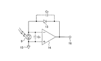
カメラ等の測光センサに用いられる光検知回路として、従来、例えば特開平5−180695号公報に開示されているものが知られている。図7を用いて上記公報に開示されている光検知回路の構成について説明する。上記公報開示の光検知回路は、図7に示すように、演算増幅器14の入力端子間に受光素子のフォトダイオード9を接続し、演算増幅器14の反転入力端子と出力端子間に対数圧縮用のダイオード13を接続し、演算増幅器14の非反転入力端子を基準電圧源15に接続して構成されている。そして、フォトダイオード9で光を受けて発生した光電流をダイオード13で対数圧縮して電圧に変換後、出力端子16より出力するようになっている。なお、ダイオード13とフォトダイオード9には、並列に寄生容量(接合容量)が付加されている。
As a light detection circuit used for a photometric sensor such as a camera, a circuit disclosed in, for example, Japanese Patent Laid-Open No. 5-180695 has been known. The configuration of the photodetection circuit disclosed in the above publication will be described with reference to FIG. As shown in FIG. 7, the photodetector circuit disclosed in the above publication has a photodiode 9 as a light receiving element connected between the input terminals of the
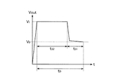
図7に示した従来の上記構成の光検知回路において、電源投入から出力電圧が安定するまでの様子を図8に示す。上記構成の光検知回路において、電源投入してから出力電圧が安定するまでに要する時間t0 は、次式(1)で表される。
t0 ={C1 ・(V1 −V0 )/A0 +C2 ・(V1 −V0 )}/i
・・・・・・・(1)
In the conventional photodetection circuit having the above-described configuration shown in FIG. 7, the state from when the power is turned on until the output voltage is stabilized is shown in FIG. In the photodetection circuit having the above configuration, the time t 0 required from when the power is turned on until the output voltage is stabilized is expressed by the following equation (1).
t 0 = {C 1 · (V 1 −V 0 ) / A 0 + C 2 · (V 1 −V 0 )} / i
・ ・ ・ ・ ・ ・ ・ (1)
ここで、A0 は演算増幅器のオープンループゲイン、C1 はフォトダイオード9の接合容量、V1 は電源投入時の出力電圧、V0 は安定後の出力電圧、C2 はダイオード13の寄生容量、iはフォトダイオード9で生成される光電流の電流値である。図8に示すように、電源投入後、時間t02の間は出力電圧がV1 であり、その後時間t01の間に出力電圧V0 に向かって安定していく。
Here, A 0 is the open loop gain of the operational amplifier, C 1 is the junction capacitance of the photodiode 9, V 1 is the output voltage when the power is turned on, V 0 is the output voltage after stabilization, and C 2 is the parasitic capacitance of the
そして、上記公報には、ダイオード13を直列にn個接続することで、寄生容量C2 をダイオード1個のときと比べて1/nの容量値にする構成が示されている。寄生容量の影響を小さくすると、電源投入時の応答時間t0 が短くなる。
しかし、上記公報に開示された光検知回路には、次のような課題がある。すなわち、上記公報開示の従来例では、フォトダイオードの接合容量C1 に起因する電源投入時の応答速度の劣化については考慮がなされていない。より低輝度で光検知回路を動作させるためには、光電流を大きくするためにフォトダイオードの面積を大きくする必要がある。フォトダイオードを大きくすると、接合容量は大きくなる。このとき、(1)式のフォトダイオードの接合容量C1 が大きくなるため、t01は大きくなり電源投入後に長い時間を待たないと出力が安定しない。 However, the light detection circuit disclosed in the above publication has the following problems. That is, in the conventional example of the above publication discloses, not been consideration for the junction capacitance C 1 response speed of degradation of the power-on due to the photodiode. In order to operate the light detection circuit with lower luminance, it is necessary to increase the area of the photodiode in order to increase the photocurrent. When the photodiode is increased, the junction capacitance is increased. In this case, (1) for formula junction capacitance C 1 of the photodiode becomes large, t 01 is output without waiting for a long time after increased and the power is turned on is not stable.
本発明は、この点に着目してなされたもので、フォトダイオードの面積が大きくなり接合容量が大きくなって電源投入時の応答速度が劣化する課題を解決できるようにした、光検知装置及びそれを用いた光学機器を提供することを目的とする。 The present invention has been made paying attention to this point, and is a photodetection device capable of solving the problem that the area of the photodiode is increased, the junction capacitance is increased, and the response speed is deteriorated when the power is turned on. An object of the present invention is to provide an optical instrument using the above.
上記課題を解決するため、請求項1に係る発明は、演算増幅器と、該演算増幅器の入力端子と出力端子との間に接続された対数圧縮特性を有する素子と、前記演算増幅器の入力端子に接続された受光素子とを有する光信号読み出し部と、電源投入時に、設定された時間内に前記出力端子の信号レベルを所定のレベルとする光量を前記受光素子に供給する光供給手段とを有して光検知装置を構成するものである。そして、この請求項1に係る発明の実施例には、実施例1が対応する。 In order to solve the above-described problem, an invention according to claim 1 is directed to an operational amplifier, an element having a logarithmic compression characteristic connected between an input terminal and an output terminal of the operational amplifier, and an input terminal of the operational amplifier. An optical signal reading unit having a connected light receiving element, and a light supply unit that supplies the light receiving element with an amount of light that sets the signal level of the output terminal to a predetermined level within a set time when the power is turned on. Thus, the light detection device is configured. The embodiment of the invention according to claim 1 corresponds to the first embodiment.
請求項2に係る発明は、請求項1に係る光検知装置において、前記光信号読み出し部は、2つの光信号読み出し部よりなり、一方の前記光信号読み出し部は、前記受光素子の前面に入射光の赤外光成分を除去するフィルタが配置され、他方の前記光信号読み出し部は、前記受光素子の前面に入射光の可視光成分を除去するフィルタが配置され、前記光供給手段は、その供給光の一部もしくは全てが2つの前記光信号読み出し部のそれぞれの前記受光素子に直接入射する位置に配置されていることを特徴とするものである。そして、この請求項2に係る発明の実施例には、実施例1が対応する。
According to a second aspect of the present invention, in the optical detection device according to the first aspect, the optical signal readout unit includes two optical signal readout units, and one of the optical signal readout units is incident on the front surface of the light receiving element. A filter that removes infrared light components of light is disposed, and the other optical signal readout unit is disposed with a filter that removes visible light components of incident light on the front surface of the light receiving element, and the light supply means includes A part or all of the supplied light is arranged at a position where it directly enters each of the light receiving elements of the two optical signal readout units. The embodiment of the invention according to
請求項3に係る発明は、請求項2に係る光検知装置において、前記一方及び他方の各々の光信号読み出し部の受光素子は、可視光乃至赤外光に感度を有する光電変換素子よりなり、前記光供給手段が、赤外光発光素子又は可視光発光素子であることを特徴とするものである。そして、この請求項3に係る発明の実施例には、実施例1が対応する。
According to a third aspect of the present invention, in the light detection device according to the second aspect, the light receiving element of each of the one and the other optical signal readout units is a photoelectric conversion element having sensitivity to visible light or infrared light, The light supply means is an infrared light emitting element or a visible light emitting element. The embodiment of the invention according to
請求項4に係る発明は、動作状態を表示するための発光素子と、請求項1〜3のいずれか1項記載の光検知装置とを有し、前記発光素子は前記光検知装置の光供給手段として用いて光学機器を構成するものである。そして、この請求項4に係る発明の実施例には、実施例2及び3が対応する。
The invention according to
請求項1に係る発明によれば、電源投入時に必要な光量の光を光検知装置の受光素子に供給することで電源投入時の応答時間を短縮することができる。請求項2に係る発明によれば、一方の光信号読み出し部及び他方の光信号読み出し部のそれぞれの受光素子に供給光が直接入射する位置に光供給手段を配置することで、各受光素子に洩れなく光を供給し電源投入時の応答時間を短縮して光検知装置を動作させることができる。請求項3に係る発明によれば、赤外光発光素子又は可視光発光素子を光供給手段として用いることで、一方の光信号読み出し部及び他方の光信号読み出し部のそれぞれに必要な光を供給し電源投入時の応答時間を短縮して光検知装置を動作させることが可能となる。請求項4に係る発明によれば、動作状態を表示するための発光素子を光検知装置の電源投入時の応答時間を短縮するための光供給手段として用いることが可能になり、これにより、光学機器の構成部品点数を削減することができる。
According to the first aspect of the present invention, the response time when the power is turned on can be shortened by supplying the light receiving element of the light detection device with a light amount necessary for turning on the power. According to the second aspect of the present invention, the light supply means is arranged at a position where the supply light directly enters each of the light receiving elements of the one optical signal readout unit and the other optical signal readout unit, so that It is possible to operate the light detection device by supplying light without leakage and shortening the response time when the power is turned on. According to the invention of
次に、本発明を実施するための最良の形態について説明する。 Next, the best mode for carrying out the present invention will be described.
(実施例1)
まず、本発明に係る光検知装置の実施例1について説明する。図1,図2,図3を用いて実施例1に係る光検知装置について説明する。実施例1は、本発明に係る光検知装置を光源種を判別する光源検知センサとしてカメラに搭載した構成例である。図1は、光源検知センサを搭載したカメラの外観図である。図1において、5はカメラボディーで、該カメラボディー5の上部の左端に電源のON,OFFを制御する電源スイッチボタン0とシャッターボタン1を備え、撮影時の光源種を判別する光源検知センサを備えた光源検知部2を交換レンズ4の左斜め上部に配置する。
Example 1
First, a first embodiment of the light detection device according to the present invention will be described. The photodetecting device according to the first embodiment will be described with reference to FIGS. Embodiment 1 is a configuration example in which a light detection device according to the present invention is mounted on a camera as a light source detection sensor for determining a light source type. FIG. 1 is an external view of a camera equipped with a light source detection sensor. In FIG. 1, a
次に、図2を用いて光源検知センサへの光の供給手法について説明する。カメラの外装6に設けられ光源検知センサ用の拡散窓7の奥に光源検知センサ8を配置する。赤外光を発光するLED12は、光源検知センサ8に対して傾いた位置から赤外光を供給する。
Next, a method for supplying light to the light source detection sensor will be described with reference to FIG. A light
光源検知センサ8は、可視光検出用の光信号読み出し部に可視光乃至赤外光に感度を有する可視光検出用フォトダイオード9-2を配置し、その光入射側に入射光の赤外光成分を除去するIRカットフィルタ10を配置している。また、赤外光検出用の光信号読み出し部に、可視光乃至赤外光に感度を有する赤外光検出用フォトダイオード9-1を配置し、その光入射側に入射光の可視光成分を除去する可視光カットフィルタ11を配置して構成する。光源検知センサ8の赤外光検出用フォトダイオード9-1の出力と可視光検出用フォトダイオード9-2の出力の比により、光源種の判別を行う。光源種の判別をした結果に基づいて、高精度なピントずれ補正や、ホワイトバランス補正を行う。
In the light
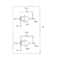
次に、図3を用いて実施例1に係る光検知装置である光源検知センサ8の光信号読み出し部について説明する。図3に示すように、赤外光検出用及び可視光検出用フォトダイオード9-1,9-2をそれぞれ演算増幅器14-1,14-2の入力端子間に接続し、ダイオード13-1,13-2をそれぞれ演算増幅器14-1,14-2の反転入力端子と出力端子16-1,16-2間に接続し、演算増幅器14-1,14-2の非反転入力端子を基準電圧源15に接続して、光信号読み出し部が構成されている。
Next, the optical signal reading unit of the light
また、図2で示した赤外光を発光するLED12は、電源スイッチボタン0をONするときに点灯して、斜め方向から光源検知センサ8に対して赤外光を照射し、IRカットフィルタ10及び可視光カットフィルタ11を通さない、必要な光量の光が、赤外光検出用フォトダイオード9-1と可視光検出用フォトダイオード9-2の両方に直接供給されるように構成する。このように、電源スイッチボタン0をONにして、それぞれのフォトダイオードに光を供給するとき、(1)式で説明した電源投入してから出力が安定するまでに要する時間t0 は、LED12から光を供給して各フォトダイオードで発生した光電流をiLED とすると、次式(2)で表される。
t0 ={C1 ・(V1 −V0 )/A0 +C2 .(V1 −V0 )}/(i+iLED )
<{C1 ・(V1 −V0 )/A0 +C2 .(V1 −V0 )}/i
・・・・・・・(2)
Further, the
t 0 = {C 1 · (V 1 −V 0 ) / A 0 + C 2 . (V 1 −V 0 )} / (i + i LED )
<{C 1 · (V 1 −V 0 ) / A 0 + C 2 . (V 1 −V 0 )} / i
(2)
(2)式からわかるように、電源スイッチボタン0をONする際にLED12から赤外光をフォトダイオードに供給することで、電源投入後に正常に動作するまでの時間を短縮することができる。
As can be seen from the equation (2), when the
(実施例2)
次に、図4の(A),(B)を用いて、実施例2について説明する。図4の(A)で示すように、実施例2に係る光検知装置を用いたカメラにおいてはカメラボディー5の上部に電源スイッチボタン0を備え、光源検知部2の下にセルフタイマー動作表示部3を配置している。図4の(A)に示したカメラにおけるセルフタイマー動作表示部3以外の構成は、図1に示した実施例1に係る光検知装置を用いたカメラの構成と同様である。実施例2は、光検知装置の光供給手段として、セルフタイマー動作表示部3に適用する発光素子を用いるものである。図4の(B)に示すように、セルフタイマー動作表示部3において、その動作を表示する発光素子19がカメラの外装6の内側に配置されている。
(Example 2)
Next, Example 2 will be described with reference to FIGS. As shown in FIG. 4A, in the camera using the light detection device according to the second embodiment, the
発光素子19には、撮影者にセルフタイマーの動作状態を表示するために、可視光乃至近赤外光の感度を有するものを用いる。投光窓17を通して発せられた光により、カメラがセルフタイマー撮影をする際やリモコン動作する際の動作状態を表示する。そして、発光素子19の漏れ光を反射部材18で反射させて、斜め方向から光源検知センサ8に光を供給するように構成する。光源検知センサ8に対して光を斜め方向から供給することで、可視光カットフィルタ11を通さない光が赤外光検出用フォトダイオード9-1に直接供給されるように構成する。一方、可視光検出用フォトダイオード9-2では、発光素子19の光は可視光に感度を持ったものであり、IRカットフィルタ10を通過せずに斜め方向から直接入射した光ばかりでなく、IRカットフィルタ10を透過した光によっても光電流が発生する。
As the
以上のように、実施例2においても、電源スイッチボタン0をONするときに発光素子19を点灯して、光源検知センサの可視光検出用フォトダイオード及び赤外光検出用フォトダイオードそれぞれで光電流を発生させることで、実施例1と同様に、(2)式に示すように光検知装置の電源投入時の応答時間を短縮できる。
As described above, also in Example 2, the
(実施例3)
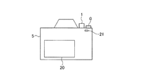
次に、図5及び図6を用いて、実施例3について説明する。実施例3は、光検知装置の光供給手段としてカードアクセス状態表示部用の発光素子を用いるものである。図5は、実施例3に係る光検知装置を用いたカメラを背面から見た図である。このカメラにおいては、電源のON,OFFを制御する電源スイッチボタン0を設けると共に、カメラのメモリカードへのアクセス状態や電源投入時に正常動作していることを表示するカードアクセス状態表示部21をカメラボディー5の背面右上部に配置し、撮影した画像を表示する液晶モニタ20をカメラ背面の中央部に配置している。
(Example 3)
Next, Example 3 will be described with reference to FIGS. In the third embodiment, a light emitting element for a card access state display unit is used as a light supply unit of the light detection device. FIG. 5 is a diagram of a camera using the light detection device according to the third embodiment as viewed from the back. In this camera, a
次に、図6を用いて、カードアクセス状態表示部21に用いる発光素子により光源検知センサ8へ光を供給する手法について説明する。この実施例3では、カードアクセス状態表示部21をカードアクセス状態表示部用の投光窓25の内側に可視光乃至赤外光の感度を有するカードアクセス状態表示部用の発光素子23を配置し、カードアクセス状態表示部用の発光素子23の漏れ光を、反射部材22,24を介して、光源検知センサ8に対して斜め方向から供給する。
Next, a method of supplying light to the light
このように構成された光検知装置を搭載したカメラにおいて、電源スイッチボタン0がONされたときに、発光素子23からの光を光源検知センサ8に対して斜め方向から供給することで、可視光カットフィルタ11を通さない光を赤外光検出用フォトダイオード9-1に、IRカットフィルタ10を通さない光を可視光検出用フォトダイオード9-2に直接供給し、実施例1と同様に(2)式に示すように、光検知装置の電源投入時の応答時間を短縮することができる。
In the camera equipped with the light detection device configured as described above, when the
なお、本発明の上記各実施例の構成は、当然、各種の変形、変更が可能であり、上記記述に限定されるものではない。また、各実施例において共通する構成要素には同一の符号を付して示している。 It should be noted that the configuration of each of the above embodiments of the present invention can be variously modified and changed, and is not limited to the above description. Moreover, the same code | symbol is attached | subjected and shown to the component which is common in each Example.
0 電源スイッチボタン
1 シャッターボタン
2 光源検知部
3 セルフタイマー動作表示部
4 交換レンズ
5 カメラボディー
6 カメラ外装
7 光源検知センサ用拡散窓
8 光源検知センサ
9-1 赤外光検出用フォトダイオード
9-2 可視光検出用フォトダイオード
10 IRカットフィルタ
11 可視光カットフィルタ
12 LED
13-1,13-2 ダイオード
14-1,14-2 演算増幅器
15 基準電圧源
16-1,16-2 出力端子
17 投光窓
18 反射部材
19 発光素子
20 液晶モニタ
21 カードアクセス状態表示部
22,24 反射部材
23 発光素子
25 投光窓
0 Power switch button 1
10 IR cut filter
11 Visible light cut filter
12 LED
13-1, 13-2 Diode
14-1, 14-2 Operational amplifier
15 Reference voltage source
16-1, 16-2 output terminals
17 Floodlight window
18 Reflective member
19 Light emitting element
20 LCD monitor
21 Card access status display
22, 24 Reflective member
23 Light emitting element
25 Floodlight window
Claims (4)
電源投入時に、設定された時間内に前記出力端子の信号レベルを所定のレベルとする光量を前記受光素子に供給する光供給手段とを有する光検知装置。 An optical signal readout unit including an operational amplifier, an element having a logarithmic compression characteristic connected between an input terminal and an output terminal of the operational amplifier, and a light receiving element connected to the input terminal of the operational amplifier;
And a light supply unit configured to supply a light amount to the light receiving element so that a signal level of the output terminal is a predetermined level within a set time when the power is turned on.
前記光供給手段が、赤外光発光素子又は可視光発光素子であることを特徴とする請求項2に係る光検知装置。 The light receiving element of each of the one and other optical signal readout units is a photoelectric conversion element having sensitivity to visible light to infrared light,
The light detection device according to claim 2, wherein the light supply unit is an infrared light emitting element or a visible light emitting element.
Priority Applications (1)
| Application Number | Priority Date | Filing Date | Title |
|---|---|---|---|
| JP2007159880A JP2008309732A (en) | 2007-06-18 | 2007-06-18 | Light detection device and optical equipment using same |
Applications Claiming Priority (1)
| Application Number | Priority Date | Filing Date | Title |
|---|---|---|---|
| JP2007159880A JP2008309732A (en) | 2007-06-18 | 2007-06-18 | Light detection device and optical equipment using same |
Publications (1)
| Publication Number | Publication Date |
|---|---|
| JP2008309732A true JP2008309732A (en) | 2008-12-25 |
Family
ID=40237456
Family Applications (1)
| Application Number | Title | Priority Date | Filing Date |
|---|---|---|---|
| JP2007159880A Withdrawn JP2008309732A (en) | 2007-06-18 | 2007-06-18 | Light detection device and optical equipment using same |
Country Status (1)
| Country | Link |
|---|---|
| JP (1) | JP2008309732A (en) |
Cited By (2)
| Publication number | Priority date | Publication date | Assignee | Title |
|---|---|---|---|---|
| US8582965B2 (en) | 2010-11-22 | 2013-11-12 | Canon Kabushiki Kaisha | Image capturing apparatus, method for controlling image capturing apparatus, and method for predicting photometric value |
| CN116457486A (en) * | 2020-11-12 | 2023-07-18 | 浦项股份有限公司 | Bake-hardening type hot-dip galvanized steel sheet excellent in powdering resistance and method for producing same |
-
2007
- 2007-06-18 JP JP2007159880A patent/JP2008309732A/en not_active Withdrawn
Cited By (2)
| Publication number | Priority date | Publication date | Assignee | Title |
|---|---|---|---|---|
| US8582965B2 (en) | 2010-11-22 | 2013-11-12 | Canon Kabushiki Kaisha | Image capturing apparatus, method for controlling image capturing apparatus, and method for predicting photometric value |
| CN116457486A (en) * | 2020-11-12 | 2023-07-18 | 浦项股份有限公司 | Bake-hardening type hot-dip galvanized steel sheet excellent in powdering resistance and method for producing same |
Similar Documents
| Publication | Publication Date | Title |
|---|---|---|
| JP5020651B2 (en) | Imaging apparatus and imaging system | |
| JP5071233B2 (en) | Camera and camera system | |
| US7595475B2 (en) | Image-pickup apparatus having a focus controller and an exposure controller | |
| US20140353501A1 (en) | Night vision attachment for smart camera | |
| JP3958055B2 (en) | Ranging and photometry equipment | |
| JP2008309732A (en) | Light detection device and optical equipment using same | |
| JP2013101362A (en) | Camera system | |
| JP2004186721A (en) | Camera | |
| JP2012168429A (en) | Image pickup apparatus | |
| JP5493640B2 (en) | Focus detection device and imaging device | |
| JP2013066051A (en) | Photographing device | |
| US6850702B2 (en) | Camera and light-receiving sensor of the camera | |
| JP6660582B2 (en) | Substance detection device and substance detection system | |
| US20230030103A1 (en) | Electronic apparatus | |
| JPH10339907A (en) | Image pickup device | |
| JPS59201009A (en) | Auto focus detecting device | |
| JP2006146081A (en) | Ranging device and imaging apparatus | |
| JP2011114442A (en) | Electronic camera | |
| JP4640108B2 (en) | camera | |
| JP4940072B2 (en) | Imaging apparatus, control method, and program | |
| JP2527978B2 (en) | Imaging device | |
| JPS60184235A (en) | Auto-focus camera | |
| JP2013164531A (en) | Imaging apparatus and control program | |
| JP2006292981A (en) | Optical device | |
| JP3845417B2 (en) | Remote control camera |
Legal Events
| Date | Code | Title | Description |
|---|---|---|---|
| A300 | Withdrawal of application because of no request for examination |
Free format text: JAPANESE INTERMEDIATE CODE: A300 Effective date: 20100907 |


