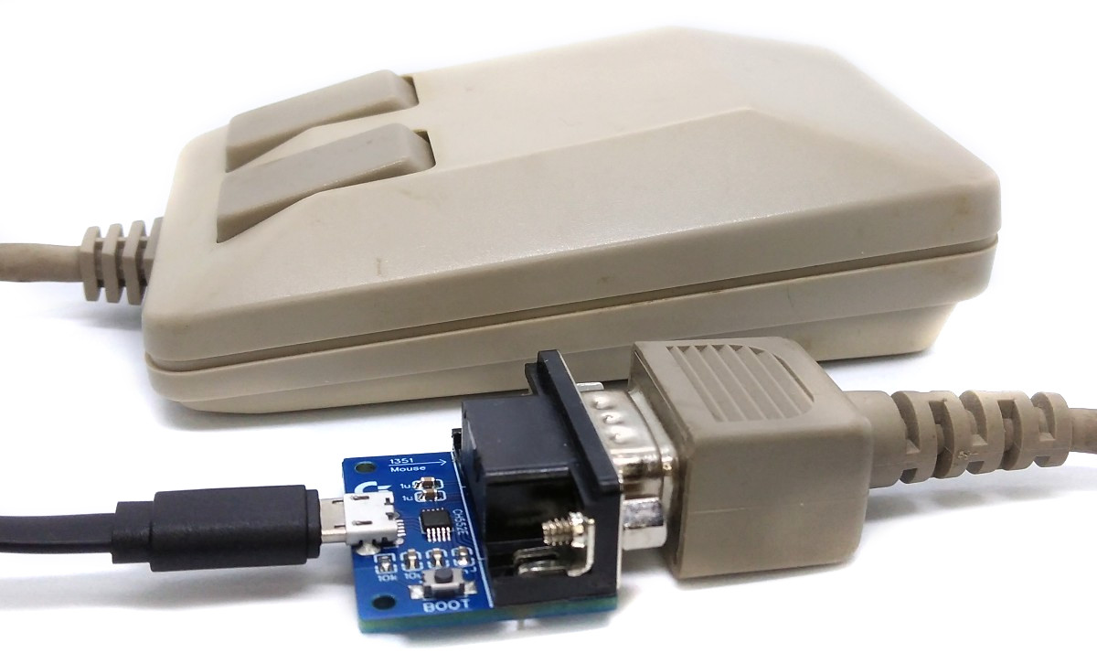
With this simple adapter, a Commodore 1351 mouse (or compatible proportional mouse) can be used on a modern PC as a USB HID device.
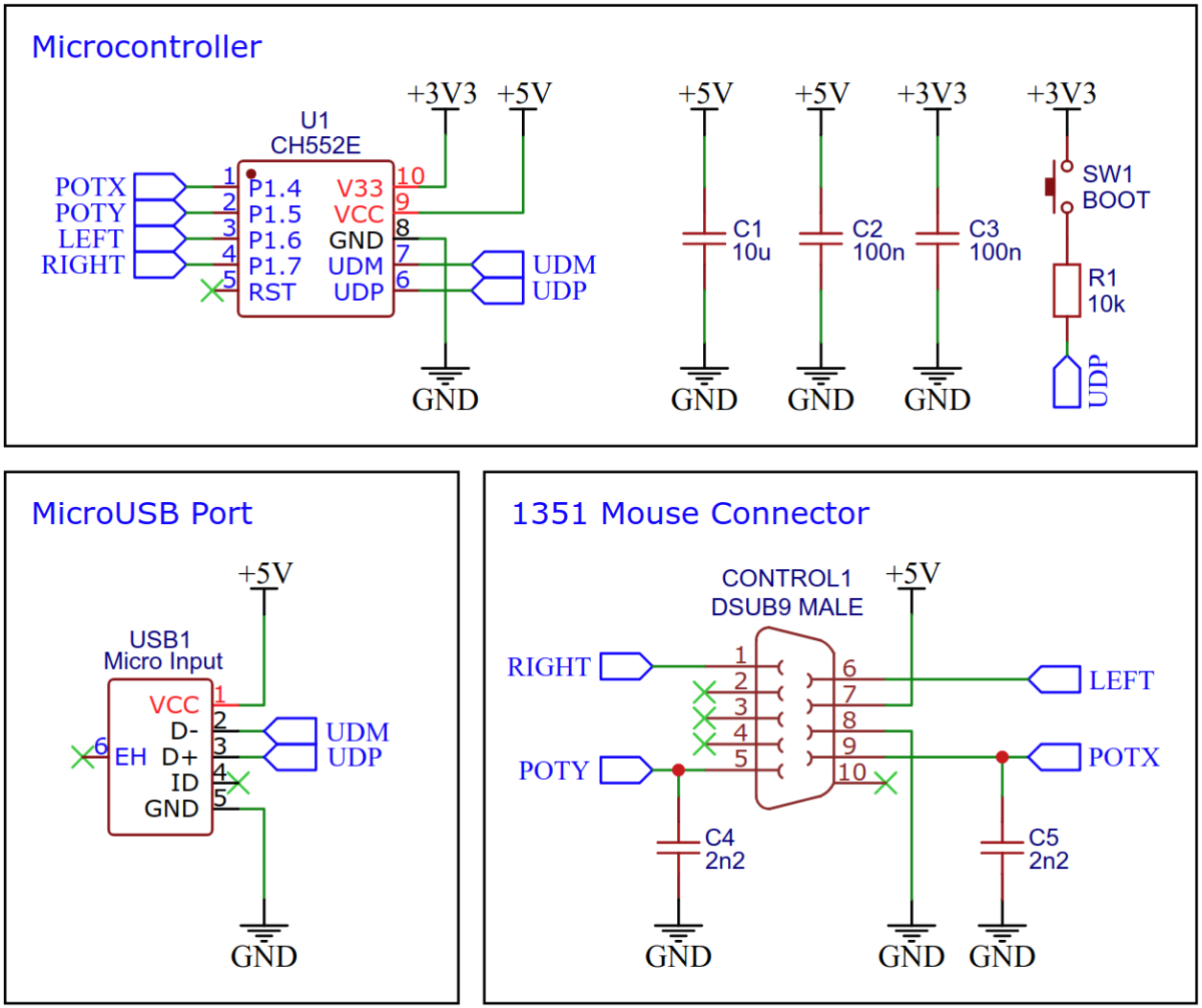
The CH552E is a low-cost, enhanced E8051 core microcontroller compatible with the MCS51 instruction set. It has an integrated USB 2.0 controller with full-speed data transfer (12 Mbit/s) and supports up to 64 byte data packets with integrated FIFO and direct memory access (DMA). The CH552E has a factory built-in bootloader so firmware can be uploaded directly via USB without the need for an additional programming device.
The 1351 is a computer mouse made by Commodore in 1986, which can be directly plugged into the 9-pin control port of a Commodore 64 or 128. In its default mode, it is a true proportional mouse, but by holding down the right mouse button when powering up the machine, it can be made to emulate its predecessor, the 1350, which acted electrically like a joystick. The 1351 mouse is not compatible with the VIC-20 or the Amiga, even though it uses the same 9-pin connector. This is because the 1351 uses the 6581/8580 SID chip's analog-to-digital converter, which is specific to the C64/C128.
The Commodore 64 features two control ports on its rightmost side. These ports are designed to allow for the connection of peripheral devices such as joysticks, paddles, mice, light pens, and sound digitizers. This feature of the Commodore 64 made it an incredibly versatile and customizable system, capable of being adapted to meet the needs of a wide range of users.
The connector used for these ports is a 9 pin d-sub male connector. This was a widely used connector in the 1980s, particularly for devices such as joysticks. The versatility of this connector meant that users could easily plug in a wide range of peripheral devices, allowing them to customize their computing experience to suit their individual needs.
| Pin | Signal | Remarks |
|---|---|---|
| 1 | Joy 0 | joystick up / right mouse button |
| 2 | Joy 1 | joystick down |
| 3 | Joy 2 | joystick left / paddle fire x |
| 4 | Joy 3 | joystick right / paddle fire y |
| 5 | Pot Y | paddle/mouse pot y |
| 6 | But A | joystick fire / left mouse button |
| 7 | + 5V | max. 100 mA |
| 8 | GND | Ground |
| 9 | Pot X | paddle/mouse pot x |
Although the 1351 mouse is commonly referred to as having an analog interface, this is not entirely accurate. It is based on the idea that the SID's analog-to-digital converter measures the time required to charge a capacitor, which would typically be done through a potentiometer in an analog paddle. By detecting the start of a measurement cycle, the capacitor can also be rapidly charged to its maximum value at any given time. However, it is up to the C64 software to determine how to interpret the measured time. The 1351 mouse software interprets these time changes as mouse movement.
To measure analog input on the C64 computer, a measurement cycle by the SID is required that takes at least 512 microseconds. During the first 256 microseconds of the cycle, the capacitor is discharged. The remaining 256 microseconds are used to wait for the capacitor to charge up to a specific voltage level (Vth). Once Vth is reached, the time is recorded and used as analog input data by the C64 software.
Instead of using a large ohmic potentiometer, a 1351 mouse rapidly charges the capacitor at intervals ranging from 320 to 448 microseconds from the beginning of the measurement cycle. If the mouse is moved right, the interval from 0μs to the time when Vth is reached on the POTX line will gradually increase up to 448μs, and then jump back to 320μs. On the other hand, if the mouse is moved left, the interval will gradually decrease until it reaches 320μs and then jump to 448μs. The speed of the mouse movement determines the rate of change.
The CH55x microcontroller in combination with two 2200pF capacitors emulates the measuring method of the SID, calculates the mouse movements and sends them as HID reports to the PC via USB.
On Linux you do not need to install a driver. However, by default Linux will not expose enough permission to upload your code with the USB bootloader. In order to fix this, open a terminal and run the following commands:
echo 'SUBSYSTEM=="usb", ATTR{idVendor}=="4348", ATTR{idProduct}=="55e0", MODE="666"' | sudo tee /etc/udev/rules.d/99-ch55x.rules
sudo service udev restart
For Windows, you need the CH372 driver. Alternatively, you can also use the Zadig Tool to install the correct driver. Here, click "Options" and "List All Devices" to select the USB module, and then install the libusb-win32 driver. To do this, the board must be connected and the CH55x must be in bootloader mode.
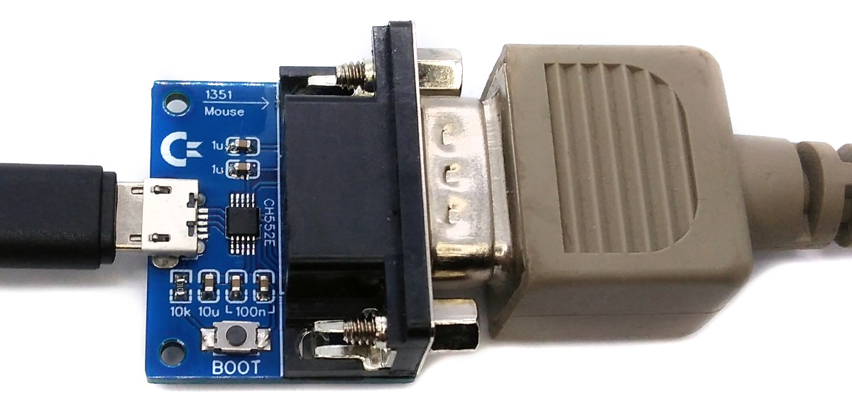
A brand new chip starts automatically in bootloader mode as soon as it is connected to the PC via USB. Once firmware has been uploaded, the bootloader must be started manually for new uploads. To do this, the board must first be disconnected from the USB port and all voltage sources. Now press the BOOT button and keep it pressed while reconnecting the board to the USB port of your PC. The chip now starts again in bootloader mode, the BOOT button can be released and new firmware can be uploaded within the next couple of seconds.
Install the SDCC Compiler. In order for the programming tool to work, Python3 must be installed on your system. To do this, follow these instructions. In addition pyusb must be installed. On Linux (Debian-based), all of this can be done with the following commands:
sudo apt install build-essential sdcc python3 python3-pip
sudo pip install pyusb
- Open a terminal.
- Navigate to the folder with the makefile.
- Connect the board and make sure the CH55x is in bootloader mode.
- Run
make flashto compile and upload the firmware. - If you don't want to compile the firmware yourself, you can also upload the precompiled binary. To do this, just run
python3 ./tools/chprog.py 1351_usb.bin.
Install the Arduino IDE if you haven't already. Install the CH55xduino package by following the instructions on the website.
- Copy the .ino and .c files as well as the /src folder together into one folder and name it 1351_usb.
- Open the .ino file in the Arduino IDE.
- Go to Tools -> Board -> CH55x Boards and select CH552 Board.
- Go to Tools and choose the following board options:
- Clock Source: 12 MHz (internal)
- Upload Method: USB
- USB Settings: USER CODE /w 0B USB RAM
- Connect the board and make sure the CH55x is in bootloader mode.
- Click Upload.

This work is licensed under Creative Commons Attribution-ShareAlike 3.0 Unported License. (http:https://creativecommons.org/licenses/by-sa/3.0/)