This guide shows how simple it is to access any FPGA Soft-IP,the I²C-, the UART-, the SPI- or CAN-Bus.
Here are also commands given to change the FPGA Fabric Configuration by using the FPGA Manager of the SoC-FPGAs.
- Turn on the HPS_LED
- The HPS_LED of the Terasic Development boards are connected to the HPS I/O-Bank of the SoC-FPGAs
- With the Linux Device Tree the Altera I/O driver assigns the I/O-Pin number to the Linux file "hps_led0"
- Type following command to turn the LED on
echo 100 > /sys/class/leds/hps_led0/brightness
- Turn off the HPS_LED
echo 0 > /sys/class/leds/hps_led0/brightness
- To toggle the HPS_LED is a blinkLed.py Python script pre-installed
- Run a exiting Python script that is located on the home-dir (~) by using
python3 blinkLed.py
- With
nano- Editor it is possible to change the scriptnano blinkLed.py
- Later a more pleasant way will be shown...
- For every rsyocto-Version an information sheet is on the
Apache Webserverpre-installed - This Paper describes the Configuration of the FPGA Soft-IP and their Addresses and the used I/O Pins of the default Configuration set was written during boot to the FPGA Fabric
- Open it by typing the iPv4-Address of your Board into a Web browser
- Of cause it is possible to install any other homepages
- Insert the homepage files to:
/usr/share/apache2/default-site/htdocsas shown in deeper guides - Restart the
ApacheServer with the following commands:/etc/init.d/apache2 stop /etc/init.d/apache2 start - Info Papers
- Insert the homepage files to:
In rsyocto all interfaces for interaction with the FPGA Fabric are activated and open during the start-up process. The following paragraph shows how easy it is to use them.
-
The
rstoolscontains a set of useful simple commands to interact and access all interfaces between the HPS (Hard processor system) and the FPGA Fabric and theFPGA-Managerof the SoC-FPGAs -
Type "FPGA" and press
TABinside your SSH-console to see all FPGA commands:FPGA-gpiReadFPGA-gpoWriteFPGA-readBridgeFPGA-readMSELFPGA-resetFabricFPGA-statusFPGA-writeBridgeFPGA-writeConfig -
The Suffix
"-h"(help) after any command gives detailed information about the rstools command -
The
rstoolsare part of mymeta-intelfpgaBSP-layer for the Yocto Project
-
Reading an AVALON-Bus FPGA Soft-IP Module connected to an ARM AXI Bridge Interface
-
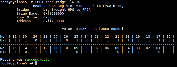
During the Boot process the FPGA-Configuration is written with a "System ID Peripheral"-component (ID: 0xcafeacdc)
-
The Module is connected via the Lightweight HPS-to-FPGA (LWHPS2FPGA; lwhps2fpga) bridge to the HPS with an address offset of 0x30
-
Use the following command to read the System ID:
FPGA-readBridge -lw 30
-
The Suffix "
-lw" selects the Lightweight HPS-to-FPGA (LWHPS2FPGA) bridge -
"30" is the (hex) address offset of the SysID Soft-IP given by the Intel Quartus Prime Platform Designer
-
The Suffix "
-b" disables a detailed output- Useful for Python-, C++- or PHP- application
FPGA-readBridge -lw 30 -b
- Useful for Python-, C++- or PHP- application
-
-
Turn off the FPGA LEDs with a single command
- The FPGA LEDs are connected via a Soft-IP "PIO (Parallel IP)" controller to the Lightweight HPS-to-FPGA bus
- For turning the LEDs off run the following command
FPGA-writeBridge -lw 20 0
- The Suffix "
-lw" selects the Lightweight HPS-to-FPGA bridge interface - "30" is the (hex) address offset of this Soft-Ip given by the Intel Quartus Prime Platform Designer
-
Put a Hex pattern to the FPGA LEDs
- With the following command any hex pattern can be written over an AXI-Bus to FPGA Soft-IP
FPGA-writeBridge -lw 20 -h acdc
- The Suffix "
-h" selects HEX value inputs
- With the following command any hex pattern can be written over an AXI-Bus to FPGA Soft-IP
-
Control a single FPGA LED
- Enabling or Disabling single Bits is also possible with the rstools
- For instance, put FPGA LED No. 7 on:
FPGA-writeBridge -lw 20 -b 7 1
- And Off:
FPGA-writeBridge -lw 20 -b 7 0
-
The next Python snippet demonstrates how to interact with FPGA Soft-IP
for count in range(1024):
    os.system('FPGA-writeBridge -lw 38 '+ str(count) +' -b')
- This git repo contains inside
examples/Pythonsome Python examples with this approach
- This git repo contains inside
-
Reading the MSEL switch
FPGA-readMSEL
- The MSEL (mode select) switch is used to give the HPS the right to access the HPS-to-FPGA Bridges and to change the FPGA-Configuration
- Also with the MSEL the type and the source of the FPGA-Configuration file is chosen
- The MSEL bit-switch is reachable over the HPS
FPGA Manager(Hard-IP part of any Intel SoC-FPGA)
-
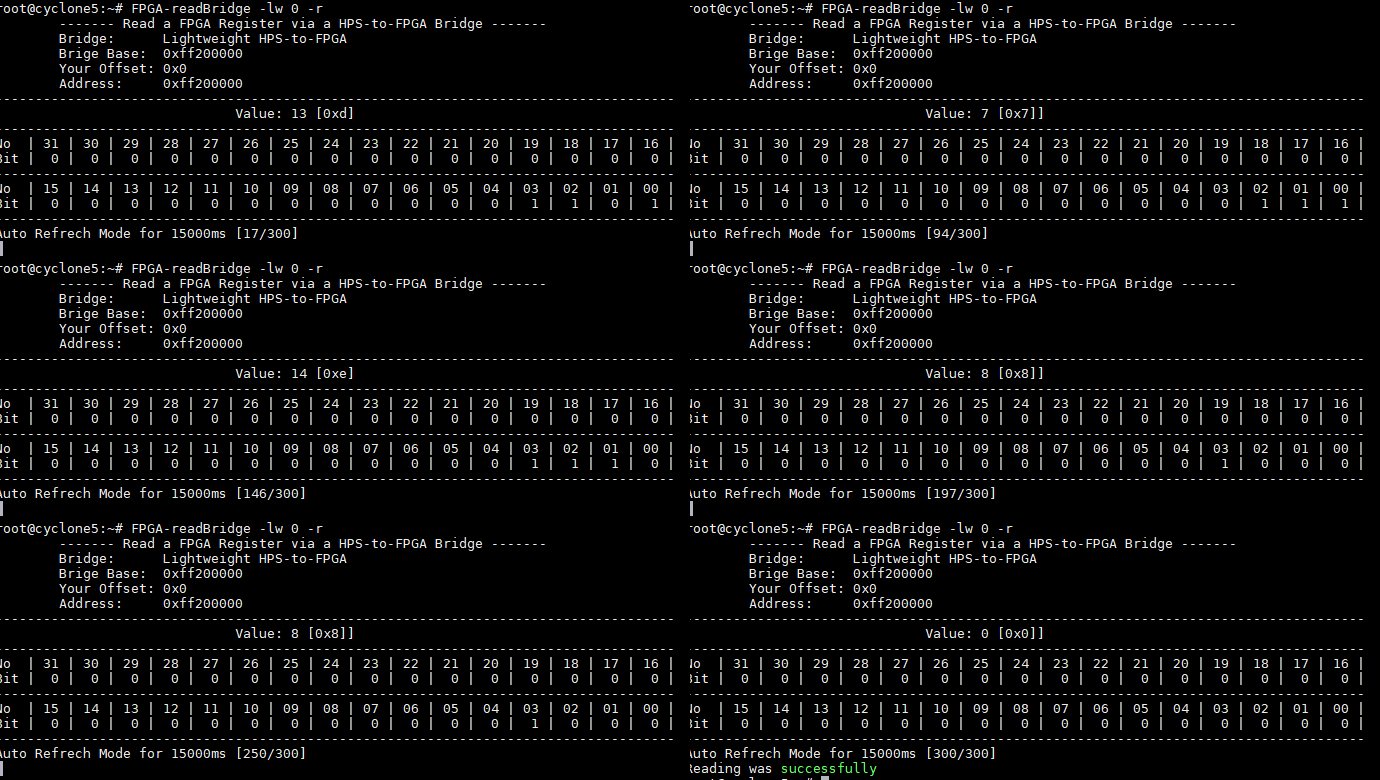
Reading the FPGA switches for 15sec
- On the LWHPS2FPGA Bridge is with the address offset 0x00 a PIO (Parallel I/O) Soft-IP module connected
- It is assigned to the FPGA switches of the development baord
- Use the following command to allow to read the FPGA switches of your board
FPGA-readBridge -lw 0
- The Suffix "
-r" allows to update the value of the register for 15secFPGA-readBridge -lw 0 -r
- For instance, updating the 4-bit switches of the Terasic DE10 Nano

-
Using the GPI/GPO- Registers to the FPGA
- Intel SoC-FPGAs have two general purpose 32-Bit registers to interact directly with the FPGA Fabric
- To test this feature connect the FPGA LEDs with the GPO-Register
- But now the FPGA LEDs are connected to Lightweight HPS-to-FPGA (LWHPS2FPGA) Bridge
- The FPGA-Configuration must be changed to reorder the FPGA LED...
- The required
.rbfConfiguration file ("gpiConf.rbf") is pre-installed on the home directory (~) - Execute the following command to re-configure the FPGA Fabric with this FPGA-Configuration file:
- For the Terasic DE10 Standard Board
FPGA-writeConfig -f gpiConfStd.rbf
- For the Terasic DE10 Nano Board
FPGA-writeConfig -f gpiConfNano.rbf
- For the Terasic DE0 Nano SoC Kit
FPGA-writeConfig -f gpiConfDe0.rbf
- For the Terasic DE10 Standard Board
- This command will check that the FPGA-Configuration file is valid for the running FPGA Fabric, then it will reset the old FPGA-Configuration, load the new FPGA-Configuration with the help of the
FPGA Managerto FPGA-Fabric and release the FPGA Fabric reset - Now should be the LEDs connected with the direct 32-Bit GPO register
- Enable the LEDs over this way
FPGA-gpoWrite -h acdc
- On the other direction the FPGA writes the value 0xacdcacdc to the HPS
FPGA-gpiRead
- After this test install the original FPGA-Configuration again
- On rsyocto the startup FPGA-Configuration is located here:
/usr/rsyocto/running_bootloader_fpgaconfig.rbf - Use the Suffix "
-r" to install the original FPGA-Configuration on the FPGA Fabric(roll back)FPGA-writeConfig -r
- Reading an AVALON-Bus FPGA Module connect to the ARM AXI HPS-to-FPGA Bridge
- During the Boot process the FPGA-Configuration is written with a "System ID Peripheral" Soft-IP component (ID: 0x23456789)
- The Module is connected via the ARM AXI HPS-to-FPGA (HPS2FPGA; hps2fpga) bridge to the HPS with an address offset of 0x00
- Use the following command to read the System ID:
FPGA-readBridge -hf 0
- The Suffix "
-hf" selects the ARM AXI HPS-to-FPGA (HPS2FPGA) bridge
- Reading to a HPS (MPU) Address to get the status of the HPS_KEY
- The
FPGA-readBridge- andFPGA-writeBridge- commands allow beside to interact with both HPS-to-FPGA bridges to access the entire memory space of the HPS (ARM Cortex-A9) (MPU =Microprocessor system) - This feature can be enabled with the attribute "
-mpu" - On the Terasic DE10- and DE0- Cyclone V SoC-FPGA boards is the HPS_KEY connected to GPIO1[24] (
GPIOB) - The "gpio_ext_portb" of
GPIO1has the address 0xFF709050 and holds the status of the HPS_KEY push button (p. 3139 of the Cyclone V SoC-FPGA HPS handbook (2018.07.17)) - Use the following command to read this Register:
FPGA-readBridge -mpu 0xFF709050
- The Suffix "
-mpu" selects the MPU (HPS) memory space (no offset will be used) - Bit number 25 is the HPS_KEY value
- The Suffix "
-r" allows to update the value of the register for 15sec - Alternately is
devmem2pre-installed as well - For this example use
devmem2 0xFF709050
- The
In rsyocto Linux drivers for all Hard-IP components are pre-installed. This was done within the Linux Device Tree and the u-boot secondary bootloader script.
Inside the pre-configured FPGA-Configuration are the HPS Hard-IP I/O pins routed over the FPGA Interconnect to FPGA I/O pins to enable the usage of Arduino Uno shields.
Typically, dedicated HPS I/O pin headers are not available on SoC-FPGA development boards. For this reason I chose this route to gain access. This can be seen inside the info papers and here. For every Hard-IP components common Linux shell tools are available.
-
I²c-Devices
- The Terasic DE10 Boards have an ADXL345-Accelerometer on
i2c0 - The
i2c-toolsallow to interact with this sensor - Scan the i²c-Bus 0 to get the i²c-Address of this sensor
i2cdetect 0
- Only the i²c-address 0x53 should be found
- With this address read the Unique ID (0xE5) of the AXDL345
i2cget -f 0 0x53 0
- Try to read the X-Axis of the accelerometer
- First enable the output of the sensor
i2cset -f 0 0x53 0x2D 8
- Then start to read the X-Axis
i2cget -f 0 0x53 0x32
- First enable the output of the sensor
- The Terasic DE10 Boards have an ADXL345-Accelerometer on
-
UART (Serial COM Port)
- For UART devices are
minicompre-installed - The following command opens the COM-Port 1 (
COM1) with minicomminicom /dev/ttys1
- This COM-Port is routed via the FPGA Interconnect to FPGA I/O Pins on the DE10 SoC-FPGA Boards
- Pres
CMD+A, thenZand thenQto leaveminicom
- For UART devices are
-
SPI
- rsyocto can be function as
SPI-Masteror as aSPI-Slave - The
spi-toolsare installed - Please follow the documentation of the spi-tools
- rsyocto can be function as
-
CAN-Bus (Intel Cylone V only)
- Intel Cyclone V SoC-FPGAs have two powerful Bosch
D_CAN-Controllers embedded - To interact with CAN Devices the
can-toolswithSocketCANare pre-installed SocketCANallows over an internal network connection to read and write CAN-Packages and monitoring their traffic- To enable the
CAN0execute this command to enable the CAN network Portip link set can0 type can bitrate 125000 ip link set up can0
- "125000" is the CAN Bitrate in Bit/s
- Sniffing the complete CAN-Bus
cansniffer can0
- Generating Dummy Payload
cangen can0
- For more information please read the can-tools documentation
- A Python example shows how to send a CAN-package with Python is also given in details here
- Intel Cyclone V SoC-FPGAs have two powerful Bosch
-
USB-Host (USB OTG)
- rsyocto enables USB Host mode (USB on-the-go) support with all boards
- For some boards are additional Micro USB OTG- (Teraisc DE10- Nano and Teraisc DE0-Nano SoC) or Mini USB-OTG (Teraisc HAN Pilot) adapters required
- Note: Before the usage of any USB devices check the required power consummation of the device and the maximum allowed of your board!
- For example to access a USB mass storage Flash drive via the USB mass storage device class (USB MSC) do the following steps
- To check that the USB device was detected use the
lsusbcommand to scan the USB Busroot@cyclone5:~# lsusb Bus 001 Device 002: ID 8564:1000 Transcend Information, Inc. JetFlash Bus 001 Device 001: ID 1d6b:0002 Linux Foundation 2.0 root hub
- Check that the USB mass storage device has a readable filesystem
root@cyclone5:~# lsblk
NAME        MAJ:MIN RM  SIZE RO TYPE MOUNTPOINT
sda           8:0    1 28.5G  0 disk
`-sda1        8:1    1 28.5G  0 part
mmcblk0     179:0    0 29.7G  0 disk
|-mmcblk0p1 179:1    0 14.2M  0 part
|-mmcblk0p2 179:2    0  3.9G  0 part /
`-mmcblk0p3 179:3    0 19.8M  0 part
/dev/sda1is here the partition of the USB Flash drive
- Mount the USB mass storage device
sudo mount /dev/sda1 /mnt
/mntis the directory the assembly point should point to
- Access the USB Flash drive with the mounting point filesystem directory (
/mnt) - Before the USB Flash drive can be removed from the board umount the mounting point
sudo umount /mnt
- To check that the USB device was detected use the
