Globally deployed WSPR Beacons - Synchronized weak signal Network - same Power - same Band hopping schedule - 80,40,20,15,10m 24x7x365. Coordinated WSPR Band hopping transmit schedule following the WSJT-X implementation
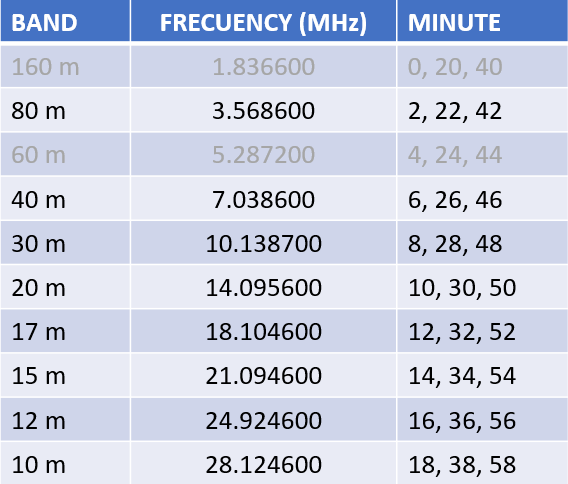
The Timetable of Int. WSPR Beacon Project
For each enabled Band the scheduler will start to transmit at the corresponding Minute.
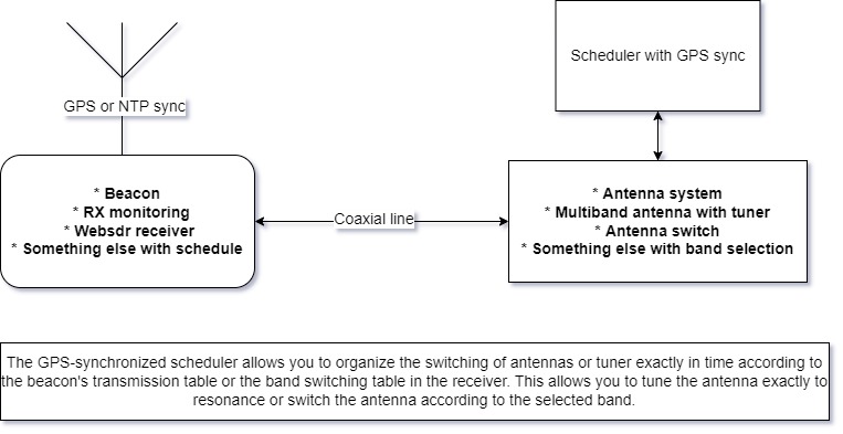
The WSPR beacon uses a transmitting antenna, which cannot be simultaneously tuned on all bands from 80 to 10 meters. SWR on different bands will not be optimal. Therefore, the question arises - how to improve this system, taking into account the fact that we are tied to the schedule.
Since we have a schedule, we can switch antennas (or matching a multiband tuner near our antenna) between bands according to the schedule. We can also use GPS signals for synchronization. Thus the scheme of this device was created.
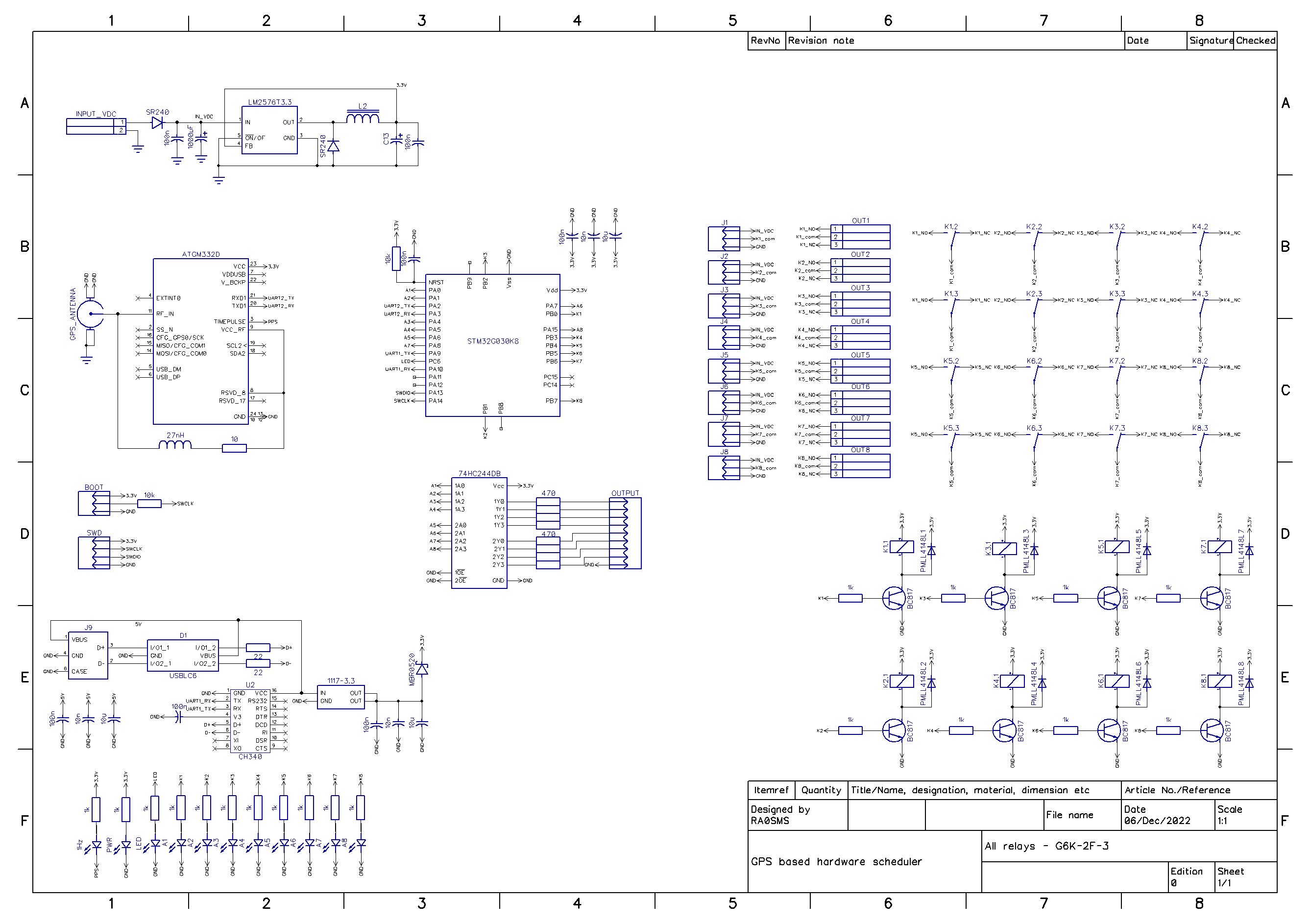
It is based on MCU STM32G030K8 and GPS receiver module ATGM332D. The source code for STM32CubeIDE you can find in code folder. The timetable for WSPR beacon is presented as arrays (see code/core/src/main.c):
/*TIMETABLE FOR ALL BANDS*/
int time80[] = {2,22,42};		//set OUTPUT 1
int time40[] = {6,26,46};		//set OUTPUT 2
int time30[] = {8,28,48};		//set OUTPUT 3
int time20[] = {10,30,50};		//set OUTPUT 4
int time17[] = {12,32,52};		//set OUTPUT 5
int time15[] = {14,34,54};		//set OUTPUT 6
int time12[] = {16,36,56};		//set OUTPUT 7
int time10[] = {18,38,58};		//set OUTPUT 8
int timeOff1[] = {0,20,40};		//reset all outputs
int timeOff2[] = {4,24,44};		//reset all outputs
The output signals are a relay output that can switch ground or supply voltage.
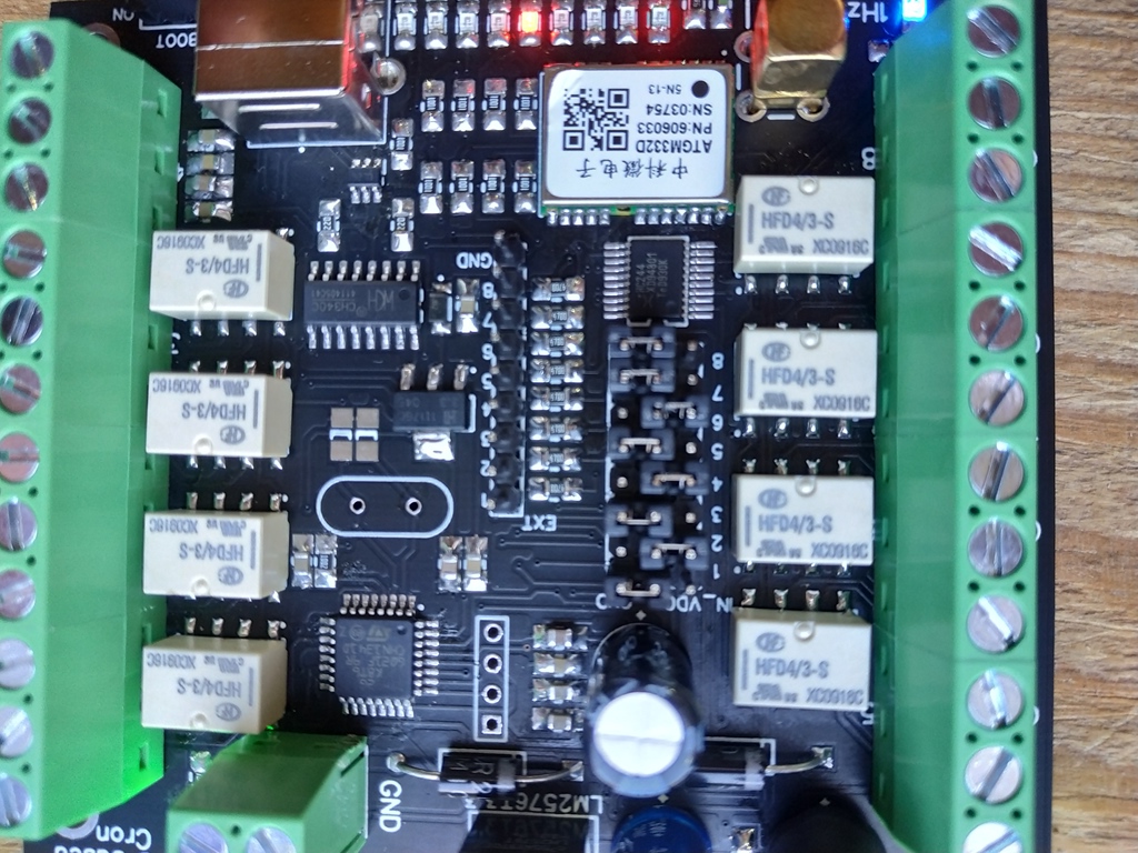
The voltage supply of the device is from 5 to 15V. The same voltage can be applied to outputs 1-8 using jumpers on the board.
IN_VDC - an active output is power supply
GND - an active output is ground.
Or you can remove any jumper and connect an external power supply to COM connector of each output.
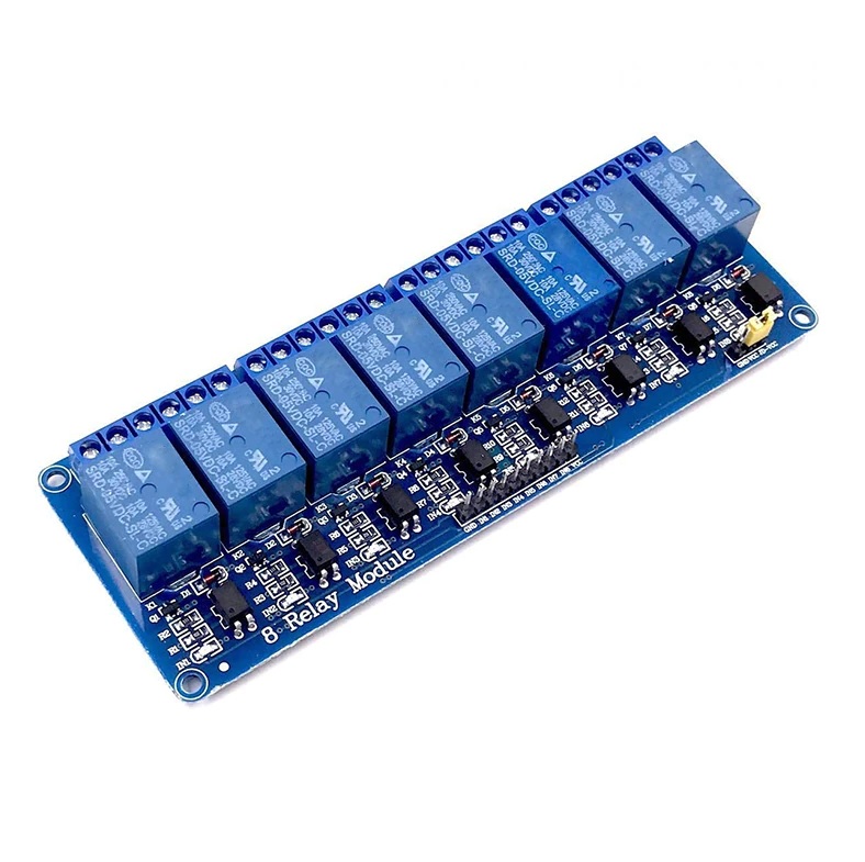
Also the devise has EXT out which can use for external relay modules, for example like this one:
EXT connector provides high logic level (3.3V) for an active output.
Power supply: 5-15VDC
Consumption current: ~25mA (12VDC)
Dimension: 78*88mm
Switched external voltage: 0-30VDC
Switched max current: 200mA
USB type B connector
RF connector for GPS antenna: SMA-F
Outputs: 8 relay outputs and 8 TTL (3.3V) outputs for an external relay module
Recommended enclosure: Gainta G311
For example, consider the case of using 8 single-band antennas and an external antenna switch (12V for switching). It is necessary to set the jumpers on all outputs to the IN_VDC position. NO contacts of outputs 1-8 connect with the control cable of the antenna switch (with the corresponding antenna ports). Connect 12V power to the board and connect the GPS antenna. The 1Hz LED on the board indicates the presence of synchronization with the GPS (it should blink once per second). LEDs 1 to 8 indicate the active output. After synchronizing with the GPS, the device will automatically switch antennas depending on the band on which it is currently transmitting.
