gpioctl has been written to provide hardware volume control for an audio engine running on the Raspberry Pi, via a rotary encoder connected to the GPIOs. It can directly interact with the ALSA mixer, or you can create JACK MIDI messages to remote-control any JACK MIDI capable client. Since it uses a generic GPIO interface via libgpiod, it might also be useful on other hardware platforms. I cannot test this personally, but your feedback is welcome.
gpioctl is written in C because it turned out that I couldn't get Python-based solutions to perform well enough to work with JACK at low latencies. If you don't need JACK, you might find Python friendlier to work with. A good example is this one: https://gist.github.com/savetheclocktower/9b5f67c20f6c04e65ed88f2e594d43c1
$ ./build/gpioctl -h

gpioctl handles switches and rotary encoders connected to GPIOs, using the
portable libgpiod kernel interface, to send text messages to /dev/stdout.
If enabled at build time, you can also send JACK MIDI CC messages,
OSC messages, or directly interact with an ALSA mixer control.
We assume GPI pins have a pull-up, so the return should be connected to ground.

-h|--help      This help.
-v|--verbose   Print current controller values.

The following options may be specified multiple times. All parameters must be
separated by commas, no spaces. Parameters in brackets are optional.

-r|--rotary clk,dt,type,...
               Set up a rotary encoder.
               clk:     the GPI number of the first encoder contact (0-63)
               dt:      the GPI number of the second encoder contact (0-63)
               Depending on 'type', the remaining parameters are:

      ...,jack,cc,[ch[,min[,max[,step[,default]]]]]
               cc:      MIDI continous controller number (0-119)
               ch:      MIDI channel (1-16), default 1
               min:     minimum controller value (0-127), default 0
               max:     maximum controller value (0-127), default 127
               step:    the step size per 'click'(1-127), default 1
               default: the initial value, default is 'min'

      ...,alsa,control[,step]
               control: the name of a simple controller in ALSA mixer
               step: the step size in dB per click, default 3

       ...,osc,url,path[,min[,max[,step[,default]]]]
               url:     The OSC url of the receiver(s), such as
                        osc.udp:https://239.0.2.149:7000
               min:     minimum value (-2147483648 - 2147483647), default 0
               max:     maximum value (-2147483648 - 2147483647), default 100
               step:    the step size per click, default 1
               default: the initial value, default is 'min'

    ...,master,url[,step]
               Set up an network master controller for use with -R.
               url:     The OSC url of the receiver(s), such as
                        osc.udp:https://239.0.2.149:7000
               step:    the step size per click, default 3

    ...,stdout,format[,min[,max[,step[,default]]]]].
               format:  a string that can contain the special tokens '%gpi%'
                        (the pin number) and '%val%' (the value)
               min:     minimum value (-2147483648 - 2147483647), default 0
               max:     maximum value (-2147483648 - 2147483647), default 100
               step:    the step size per click, default 1
               default: the initial value, default is 'min'

-s|--switch sw,type...
               Set up a switch.
               sw:      the GPI pin number of the switch contact (0-63)
               Depending on 'type', the remaining parameters are:

      ...,jack,cc,[ch[,toggle[,min[,max[,default]]]]]
               cc:      MIDI continous controller number (0-120)
               ch:      MIDI channel (1-16), default 1
               toggle:  can be 0 (momentary on) or 1 (toggled on/off)
               min:     controller value when open (0-127), default 0
               max:     controller value when closed (0-127), default 127
               default: the initial value, default is 'min'

      ...,alsa,control
               control: the name of a simple controller in ALSA mixer
                        (switch will operate the MUTE function)

       ...,osc,url,path[,toggle[,min[,max[,default]]]]
               url:     An OSC url, such as osc.udp:https://239.0.2.149/gpioctl/level
               path:    An OSC path, such as /mixer/level
               toggle:  can be 0 (momentary on) or 1 (toggled on/off)
               min:     value when open (-2147483648 - 2147483647), default 0
               max:     value when closed (-2147483648 - 2147483647), default 100
               default: the initial value, default is 'min'

    ...,master,url
               Set up a network master controller for use with -S.
               url:     The OSC url of the receiver(s), such as
                        osc.udp:https://239.0.2.149:7000

    ...,stdout,format[,toggle[,min[,max[,default]]]]
               format:  a string that can contain the special tokens '%gpi%'
                        (the pin number) and '%val%' (the value)
               toggle:  can be 0 (momentary on) or 1 (toggled on/off)
               min:     minimum value (-2147483648 - 2147483647), default 0
               max:     maximum value (-2147483648 - 2147483647), default 1
               default: the start value, default is 'min'

-U|--osc-url   URL to listen to, e.g. osc.udp:https://239.0.2.149:7000
               This is mandatory if -R or -S are used.

-R|--rotary-slave control
               control: an ALSA mixer simple control

-S|--switch-slave control
               control: an ALSA mixer simple control (operates MUTE)

Pin numbers above are hardware GPIO numbers. They do not usually correspond
to physical pin numbers. For the RPi, check https://pinout.xyz/# and look
for the Broadcom ('BCM') numbers.
libgpiod does not know how to control the pull-up/pull-down resistors of your
GPIO pins. Use a hardware-specific external tool to enable them, or add
physical pull-ups.

gpioctl is meant to run as a daemon. Use CTRL-C or send a SIGTERM to exit.
For testing, I'm using an ALPS incremental rotary encoder (model no. EC11E15244C0) with push-down switch. This one has three pins on one side for the rotary (clk, ret, dt), and two on the other for the switch (sw, ret).
A rotary works with two switches which open and close slightly out-of-phase. If you get an edge interrupt on [clk] and both switches are the same (either open or closed), you know you just went one click clockwise. If the switches are in opposite states, you went one click counter-clockwise.
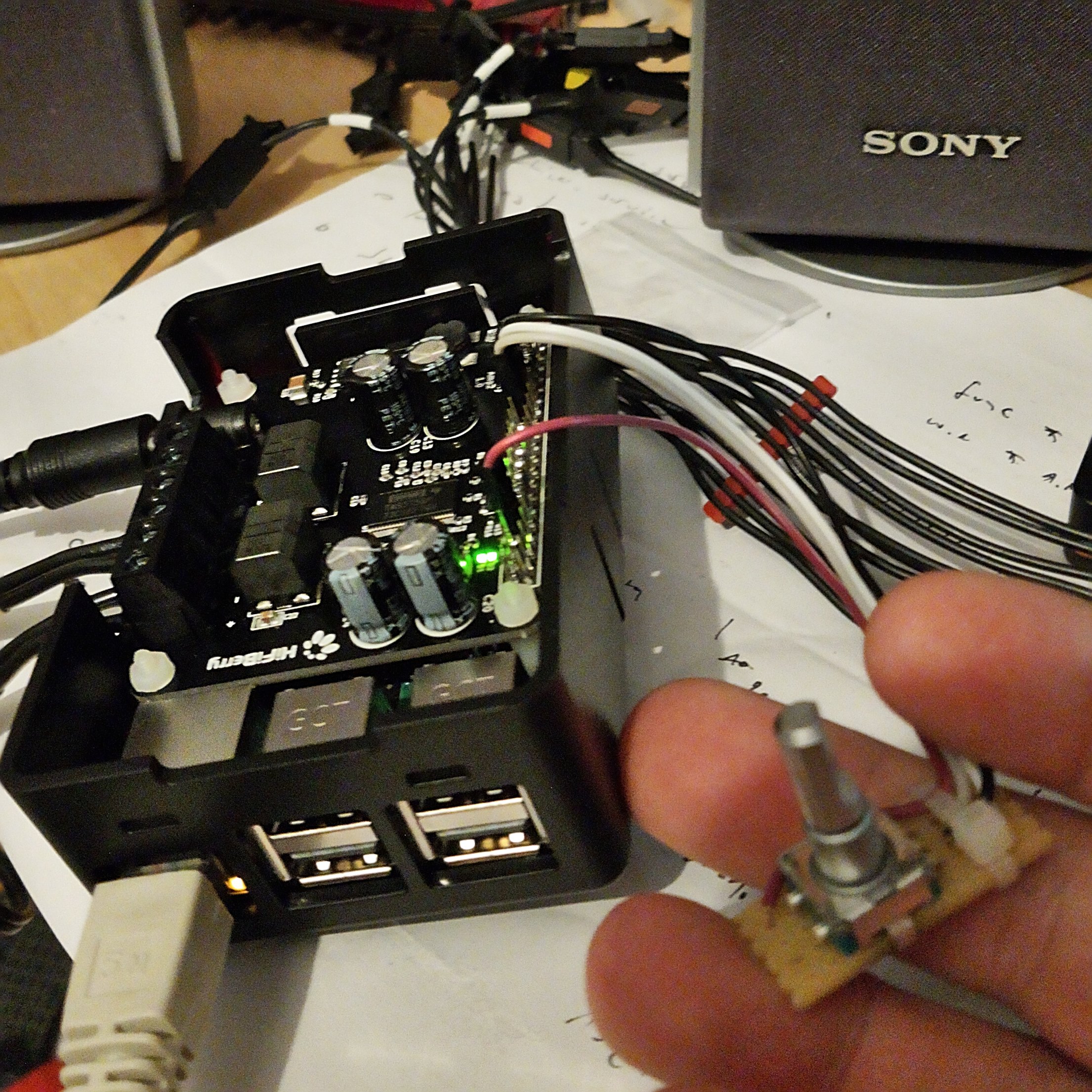
Here's a Raspberry Pi 3B+ with a HifiBerry AMP2 the ALPS rotary encoder/switch connected to the GPIOs. I'm using GPIOs 17 (white), 27 (grey), 6 (purple) in this example, the ground is black. Check out the pins at https://pinout.xyz/#.
The wiring side: the rotary connections are visible on the left, with the return pin in the middle tied to the return of the switch and grounded. The solder blobs at the top and bottom don't do anything, they just secure the encoder case in place.
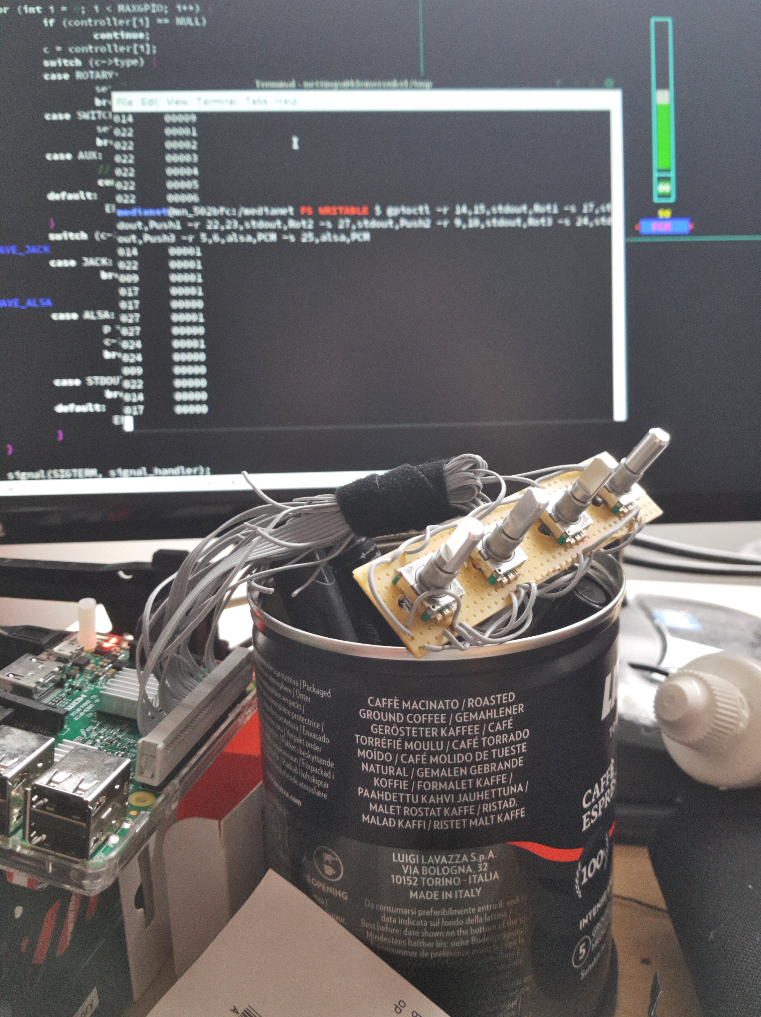
In case you were wondering: you can use as many encoders as you have GPIs (tested to up to four):
libgpiod will set the pin direction to "input" automatically, but it is not currently able to set other pin features. So you will have to use a hardware-specific tool to enable pull-ups, or connect your controller board to an appropriate voltage source and add physical pull-ups.
On the Raspberry Pi, you can use the gpio command that comes with
wiringpi:
$ sudo apt-get install wiringpi         # if you don't have it yet
$ gpio -g mode 17 up
$ gpio -g mode 27 up
$ gpio -g mode 6 up
AFAIK, it is not possible to read out the state of the pull-ups on the Pi,
but you can verify the correct setting by running gpio readall and then
run it again after moving the rotary by one click or while holding down the
switch. The value ("V") column should change.
If your pin requirements do not change at runtime, you can also preconfigure your pin states via /boot/config.txt.
In order to find the right mixer control, play some music and look at
$ amixer scontrols
Then try to manipulate a control with
$ amixer sset [YOURCONTROL] 30%
and see if the playback volume changes.
Once you've found the appropriate control name, plug it into the following command instead of "Digital", which is the default for HifiBerry AMP2 users. Now you can run
$ gpioctl -v -r 17,27,alsa,Digital -s 6,alsa,Digital
You can also run
$ watch -n 0.5 amixer sget [YOURCONTROL]
or
$ alsamixer
in another terminal and watch the mixer update live.
Start a JACK server. Then open another terminal and run
$ jack_midi_dump
which will dump all incoming JACK MIDI messages to the screen.
In a third terminal, run
$ gpioctl -v -r 17,27,jack,1,15 -s 6,jack,1,16,1
If all goes well, you should see two new jack clients, which you connect:
$ jack_lsp
system:playback_1
system:playback_2
midi-monitor:input
gpioctl:midi_out
$ jack_connect gpioctl:midi_out midi-monitor:input
Now use the controls and watch the JACK MIDI events coming in. Of course the point is to use another JACK client that does useful things with those controller inputs. Ardour or mod-host are examples.
There is now experimental support for sending OSC messages. To try it out, make sure your firewall is not blocking the respective port and IP. Here is a multicast example, it's extra fun if you run the following on several other hosts in the local network:
$ oscdump osc.udp:https://239.0.0.254:3000
Then, on the machine that has the rotary connected, try this:
$ gpioctl -r 17,27,osc,osc.udp:https://239.0.0.254:3000,/some/path/maybelevel,0,100,1,0 -s 6,osc,osc.udp:https://239.0.0.254:3000,/some/path/maybemute,1,0,1,0
This example will send the commands to a multicast IP, so that it can be received by multiple hosts. Of course you can also use normal IPs. The data type will always be 'i'.
If you have multiple nodes with soundcards that you wish to control as a group, you can use the Master/Slave mode via UDP multicast. On your "master", i.e. the one that has the rotary hardware, do
$ gpioctl -r 17,27,master:osc.udp:https://239.0.0.254:3000,4 -s 6,master/osc.udp:https://239.0.0.254:3000
and on the slave(s), do
$ gpioctl -U osc.udp:https://239.0.0.254:3000 -R Digital -S Digital
If your master machine also has a soundcard that should follow, it can be its own slave, like so:
$ gpioctl -U osc.udp:https://239.0.0.254:3000 -R Digital -S Digital -r 17,27,master,osc.udp:https://239.0.0.254:3000,4 -s 6,master,osc.udp:https://239.0.0.254:3000
If your slave has a card with multiple channels such as the AudioInjector Octo, you can link multiple channels to your slave instance:
$ gpioctl -U osc.udp:https://239.0.0.254:3000 -R DAC1 -R DAC2 -R DAC3 -R DAC4
(The Octo does not have a mute switch in its mixer, so we only use faders here.)
Note that liblo does not reliably support IPv6 multicast, and that TCP support in gpioctl should be considered broken.
The most simple way of using gpioctl is to have it spit out controller values to standard output. The formatting option is currently not implemented and will be ignored. In its current state it makes little sense, and even less when you have -v or DEBUG mode active.
$ gpioctl -r 17,27,stdout,FOOBAR -s 6,stdout,FOOBAR,1
In addition to the usual system header files and libraries, gpioctl requires
libgpiod-dev. If you want to use JACK MIDI, you need libjack-jackd2-dev
or libjack-dev (untested). If you want to access the ALSA mixer, you need
libasound2-dev. If you want to send OSC messages, you need liblo-dev and
liblo-tools.
I recommend installing wiringpi on the Pi or another hardware-specific GPIO
controller tool for your platform. (Package names are for Raspbian, they may
differ on your system.)
The build system is waf. My understanding of it is very limited. For now, from the root your working copy do
$ CFLAGS="-DDEBUG -g -Wall" ./waf configure  # for very verbose output, or
$ ./waf configure                            # for production code, or
$ ./waf configure --prefix=/foo              # if you don't like /usr/local/, and
$ ./waf                                      # to build
During the configuration step, you can selectively disable unneeded features with
--disable-{alsa|jack|osc}.
You can run it without installing from ./build/gpioctl, or install it with
$ sudo ./waf install                         # installs to prefix set before, or
$ sudo ./waf install --destdir=/bar          # for packagers


