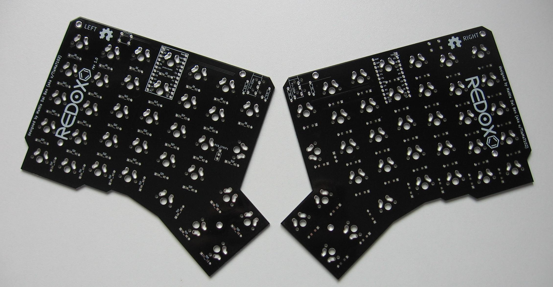
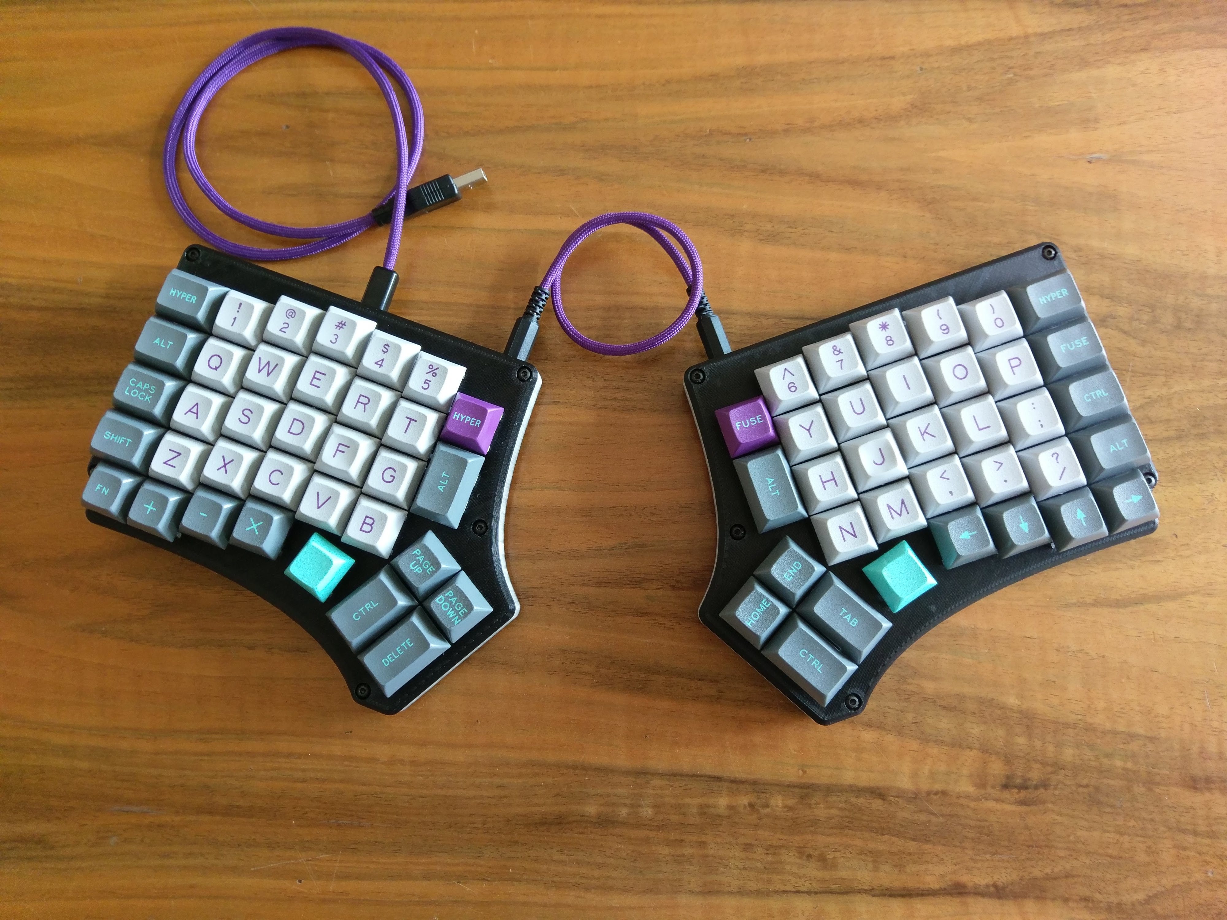
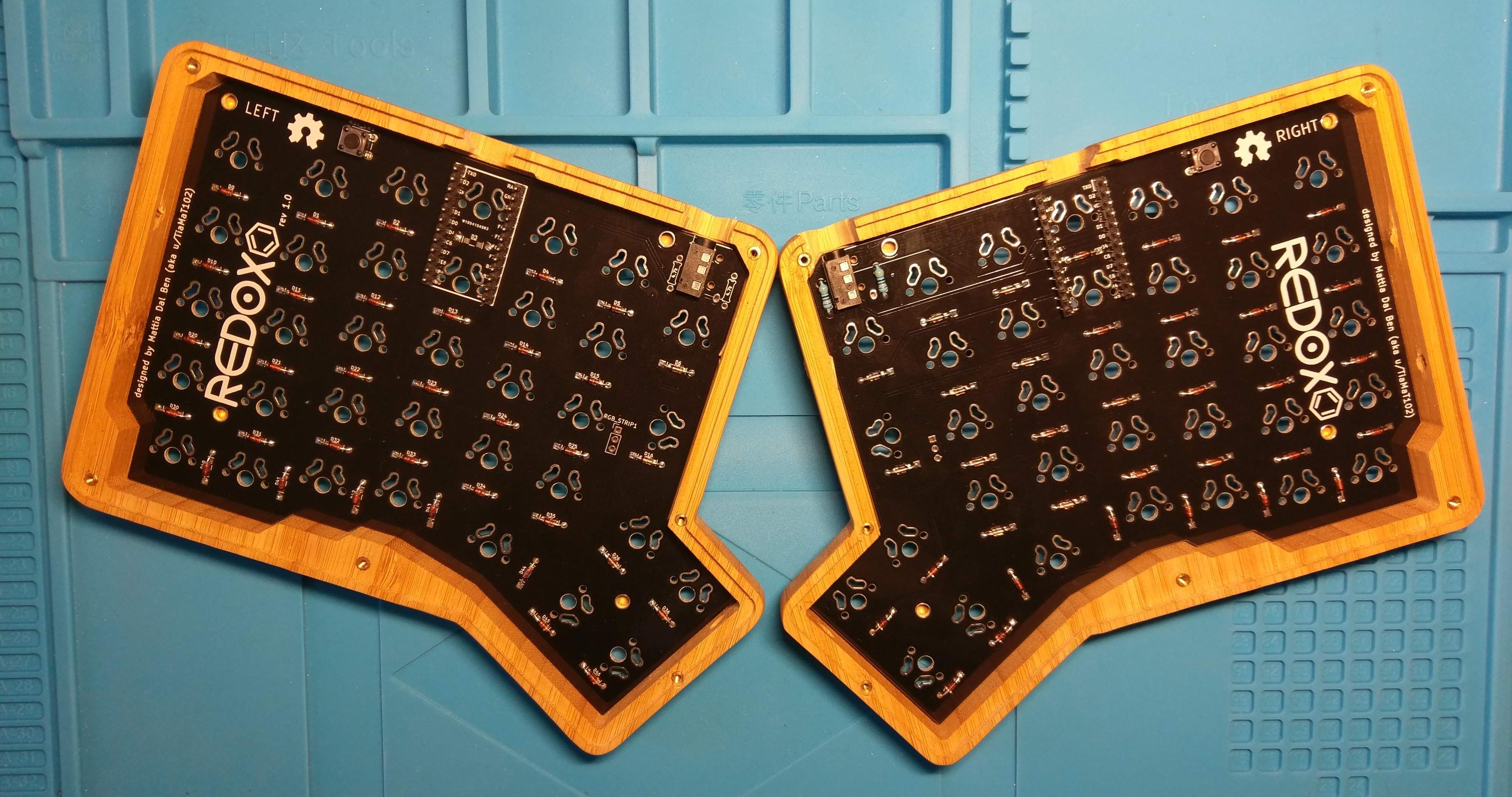
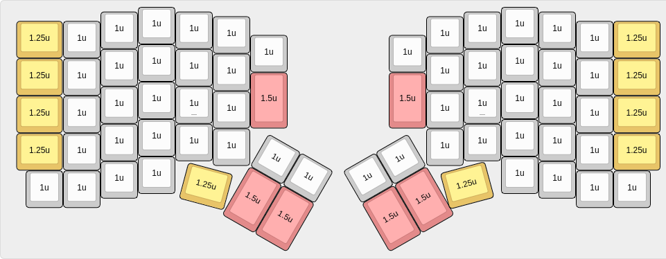
The Redox rev 1.0 is the first commercially available version of the Redox keyboard.
Hardware availability:
| Qty | Item | Notes |
|---|---|---|
| 70 | Cherry MX compatible switches | |
| 2 | Redox PCBs | Available here |
| 70 | 1N4148 diodes | SMD diodes can also be used |
| 2 | PJ-320A 4 poles 3.5 mm TRRS connectors | |
| 2 | 4.7 kOhm resistors | Need to be soldered on one half only |
| 2 | Through hole momentary switch | Dimensions 6mm x 6mm x 4.3mm |
| 2 | Arduino Pro Micro compatible microcontrollers | Beware of the infamous Green Pro Micro, see note below. |
| 1 | TRRS cable | |
| 1 | USB micro cable | |
| 70 | Cherry MX compatible keycaps | 10x 1.25u keycaps, 6x 1.5u keycaps, 54x 1u keycaps |
| 14 | WS2812/WS2812B leds | Optional RGB-underglow |
⚠️ Pay attention to the Pro Micro you use in this project. Online you can find the infamous Green Pro Micros which have the same pinout of the normal Pro Micro but use a different power circuitry. Being the Redox a split keyboard that relies on detecting which side is directly powered to find which side is the master, these clones are not suited for the task. A more detailed explanation here. Please note that they can come in different colors, not necessarily green.
⚠️ Before you start, flash the Firmware to the ProMicros to make sure they are alright.
External links to some other guides to building the Redox keyboard:
- "Build your own keyboard" by @costask.
- Imgur build log (3D printed case).
- "First Homebrew Keyboard -redox Build Log-" by インケンch (Japanese only)
- "Split Keyboard Build" by Kuba Misiorny @kubami.
- Wooden case build with hand tools by Cédric Bosdonnat
Two great video guides by インケンch (Japanese only).
Another great guide by Antonio Raptors (Spanish only).
Installation steps:
- Solder components:
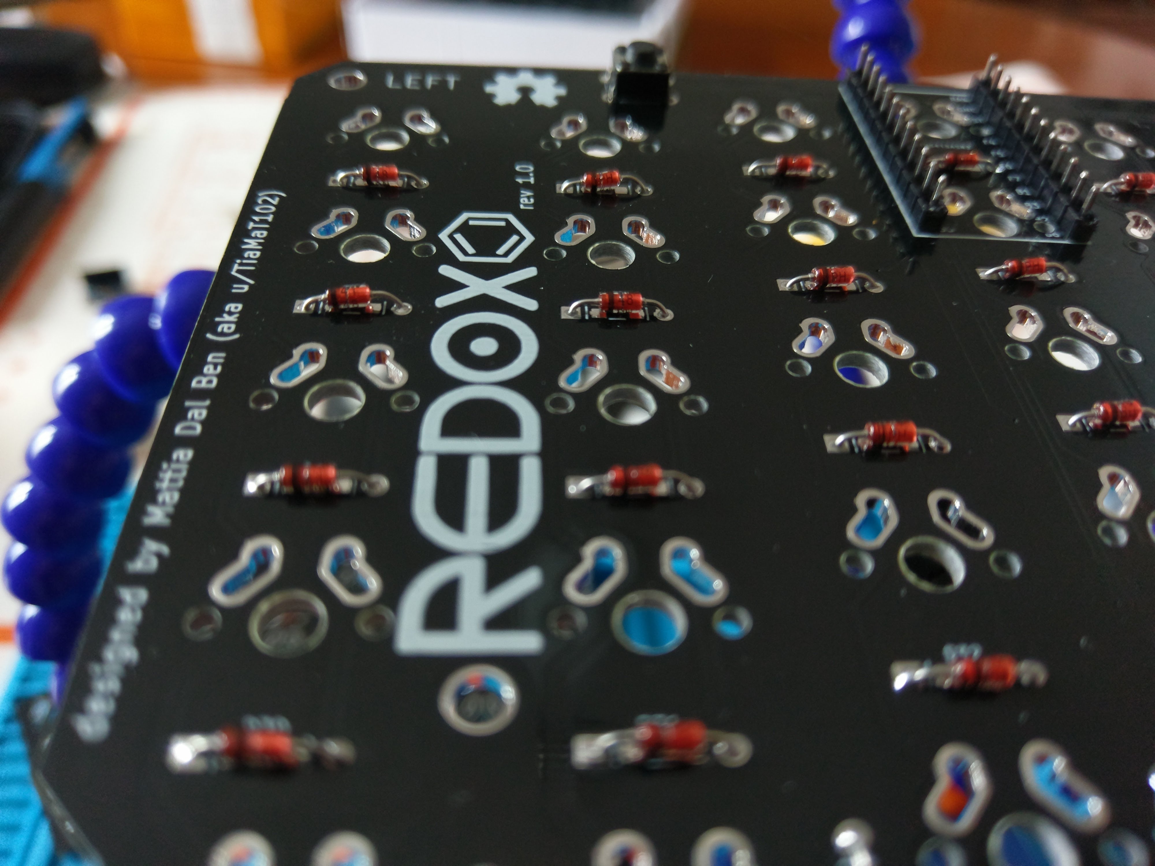
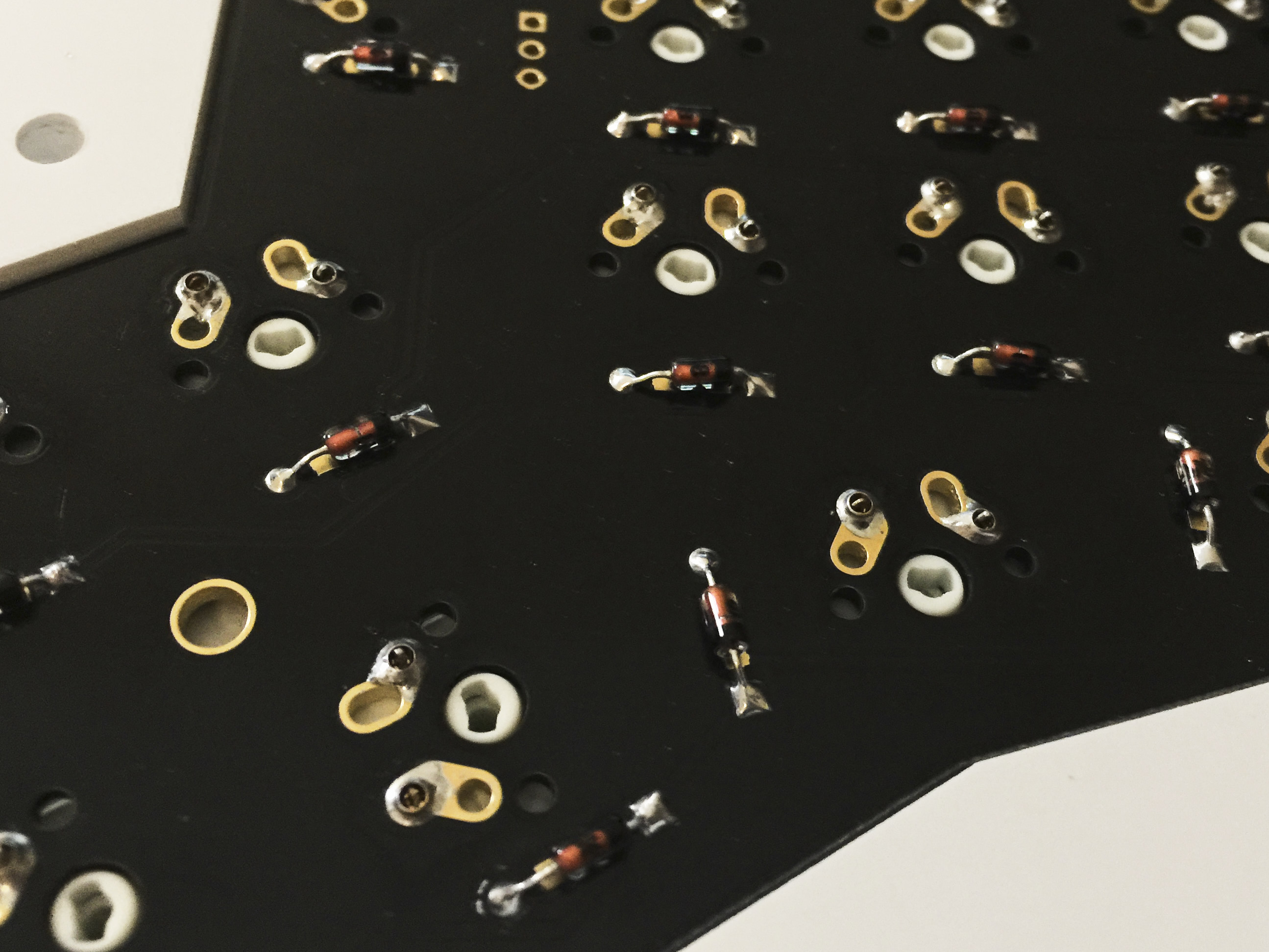
- Solder 1N4148 diodes. Keep the diode legs for the right hand controller installation.
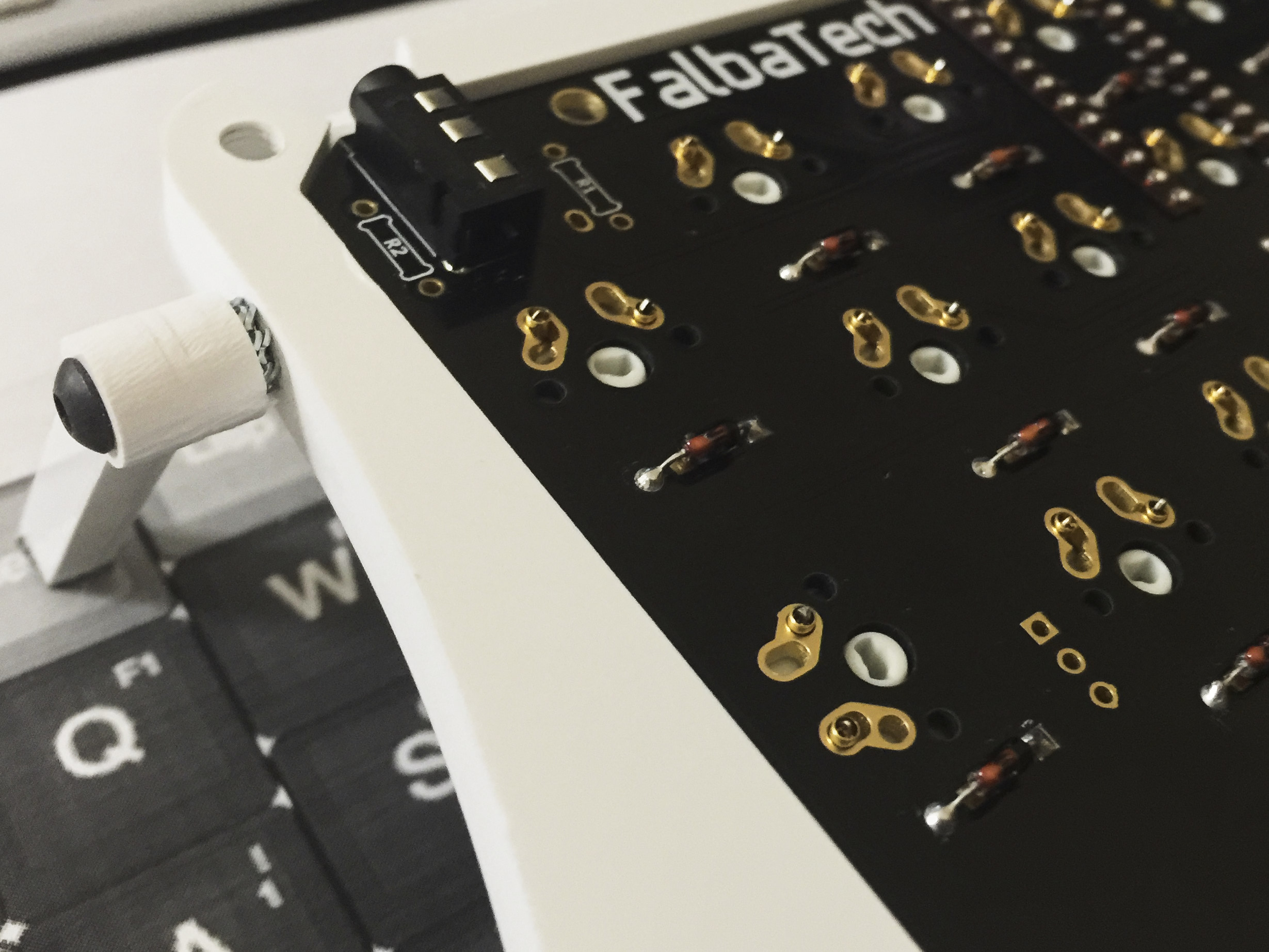
- Solder PJ-320A connectors.
- Solder momentary switches.
- Solder 4.7k Ohm resistors on one half only. If you are going for the RGB-underglow ignore this step.
- Solder the Pro Micro header pins (do not solder the Pro Micro controllers yet). This step may differ depending on which case you're using. Refer to the following:
- See 3D-Printed case right hand controller installation detail.
- See Falbatech's bamboo case.
- See socketed Pro Micro installation guide.
- Optional see RGB-underglow instructions.
- Flip the PCBs.
- Solder switches to the PCB.
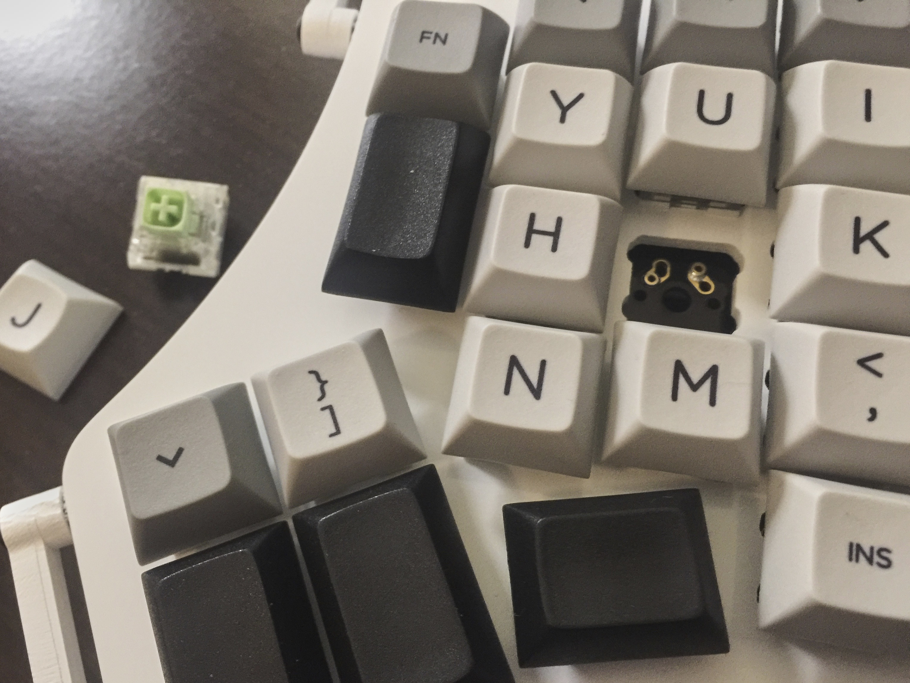
- If you want hot swappable switches, see the hot swappable switch instructions.
- Flip the PCBs again.
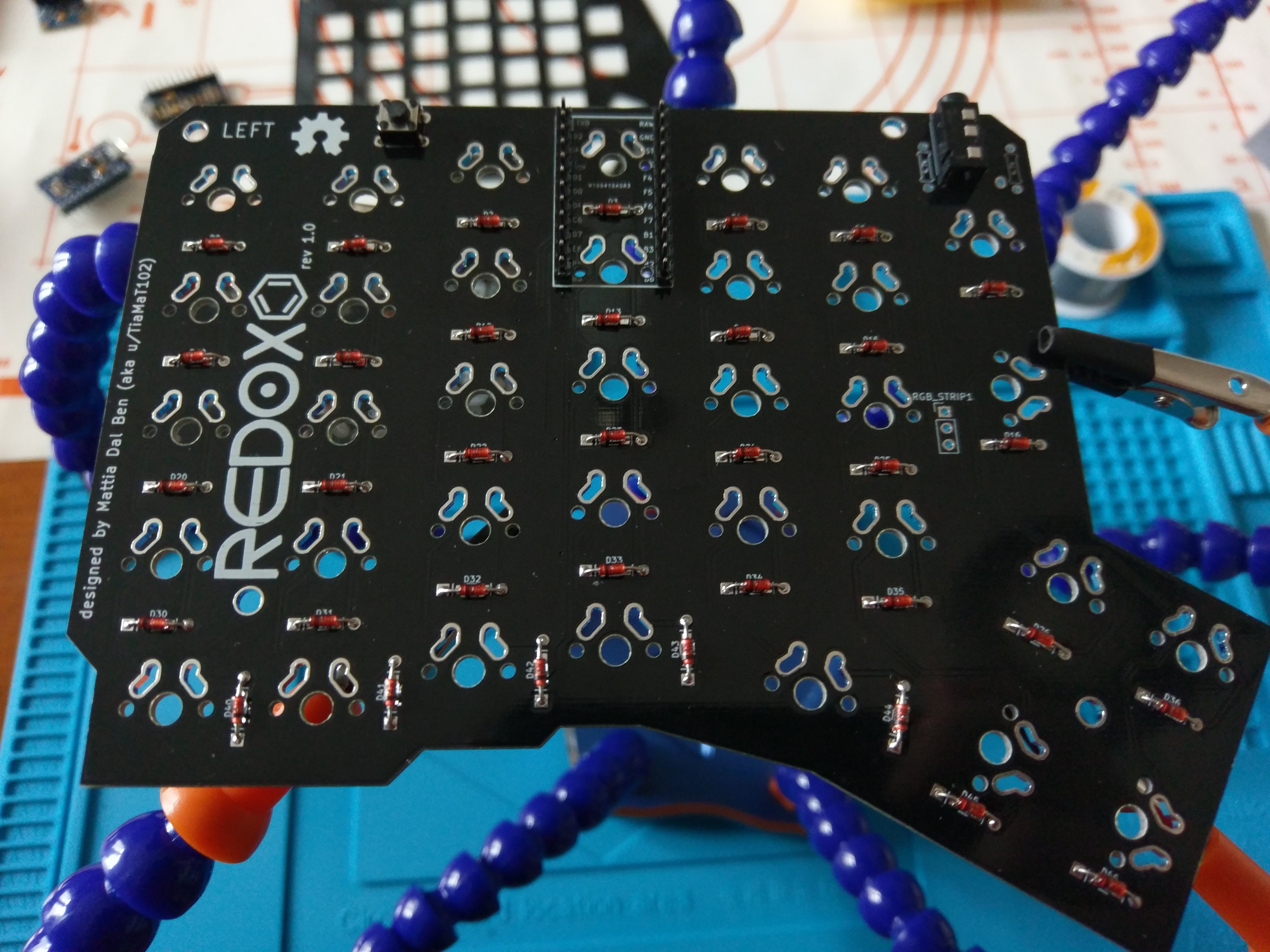
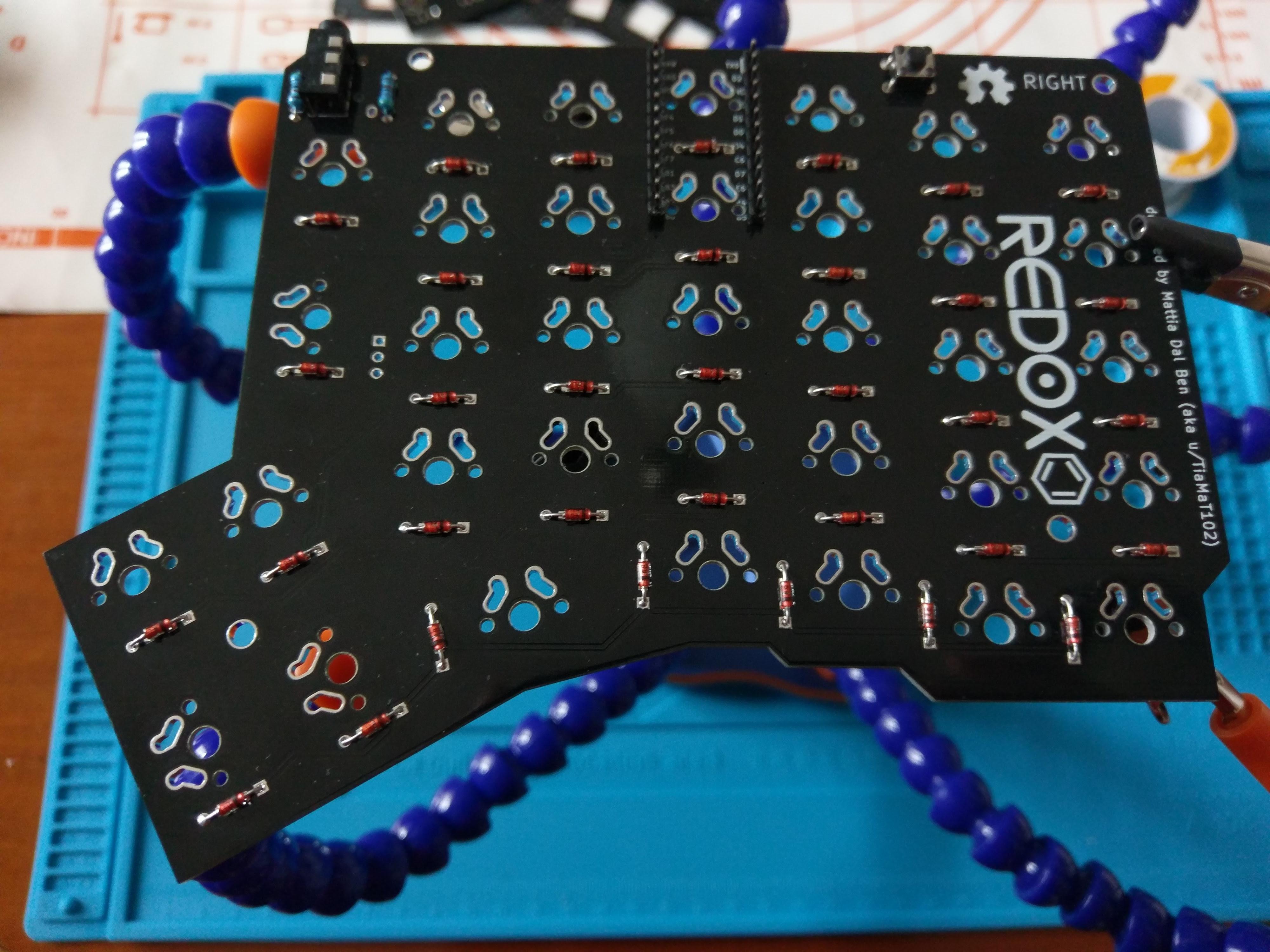
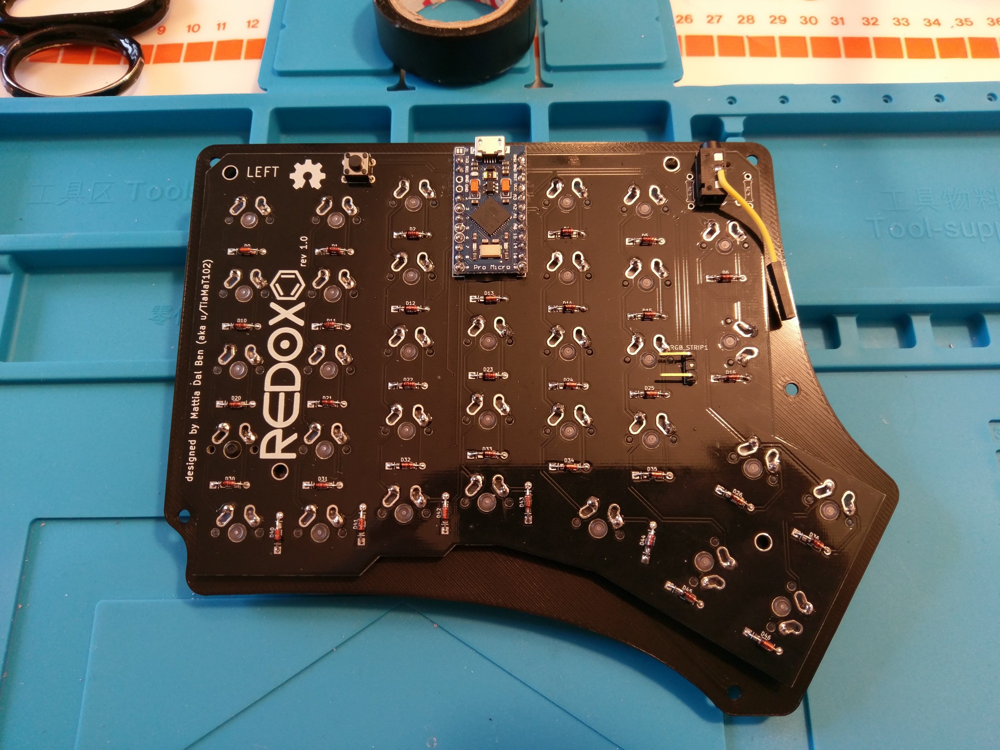
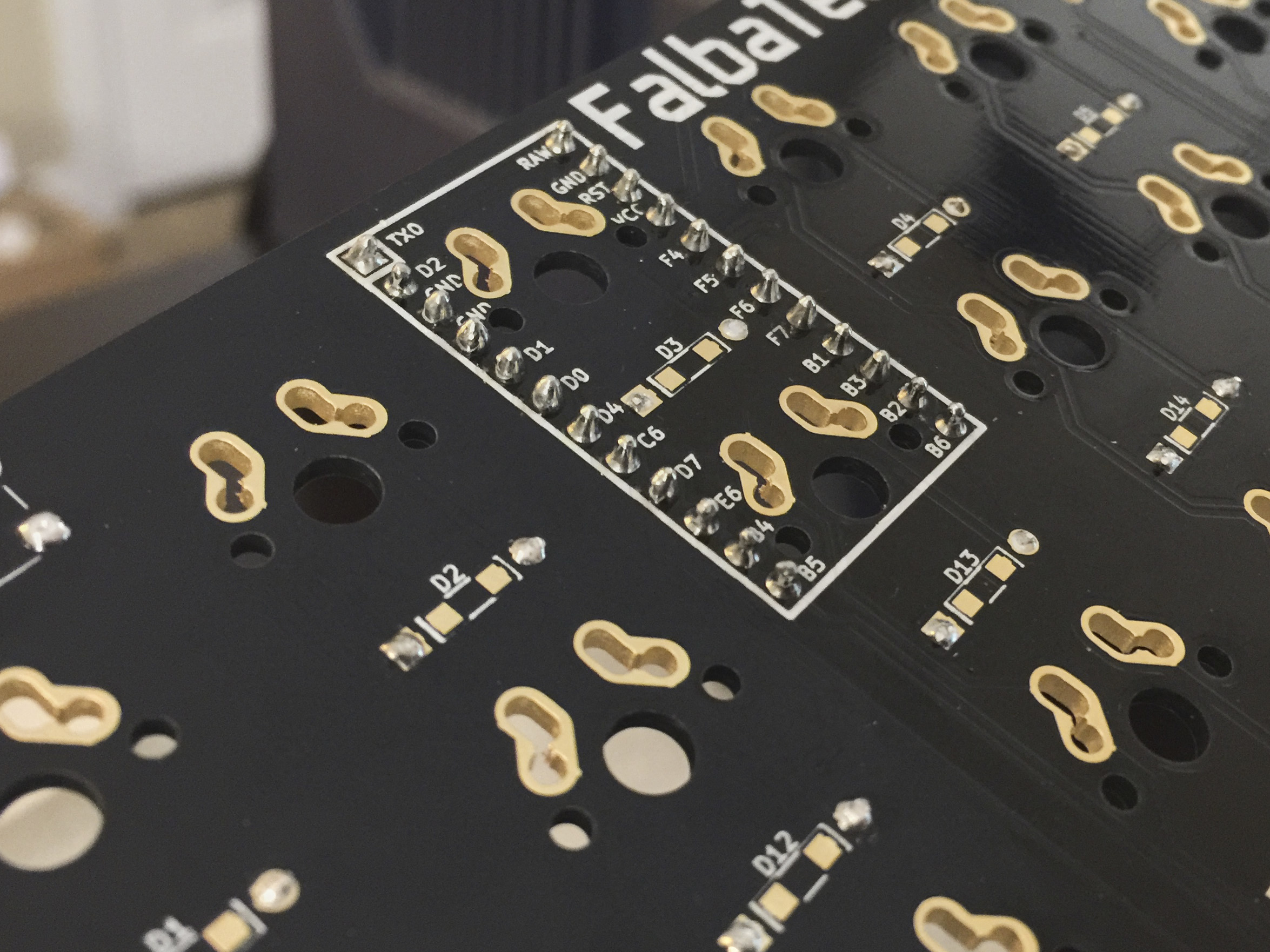
- Solder Pro Micros to the header pins following the PCB labeling. The Pro Micro on the right half should be installed with the bottom facing the Redox PCB, the Pro Micro on the left half should be installed with the bottom facing away from the PCB. See pictures for details.
To lower the build costs I designed a 3D printable case which you can find in this repository or on thingiverse, feel free to modify it to best suit your needs.
Parts:
| Qty | Item | Notes |
|---|---|---|
| 1 | Left top plate | RedoxRev1TopLeft.STL |
| 1 | Left bottom | RedoxRev1BottomLeft.STL |
| 1 | Right top plate | RedoxRev1TopRight.STL |
| 1 | Right bottom | RedoxRev1BottomRight.STL |
| 10 | M3 x 8mm (or 5mm) screws |
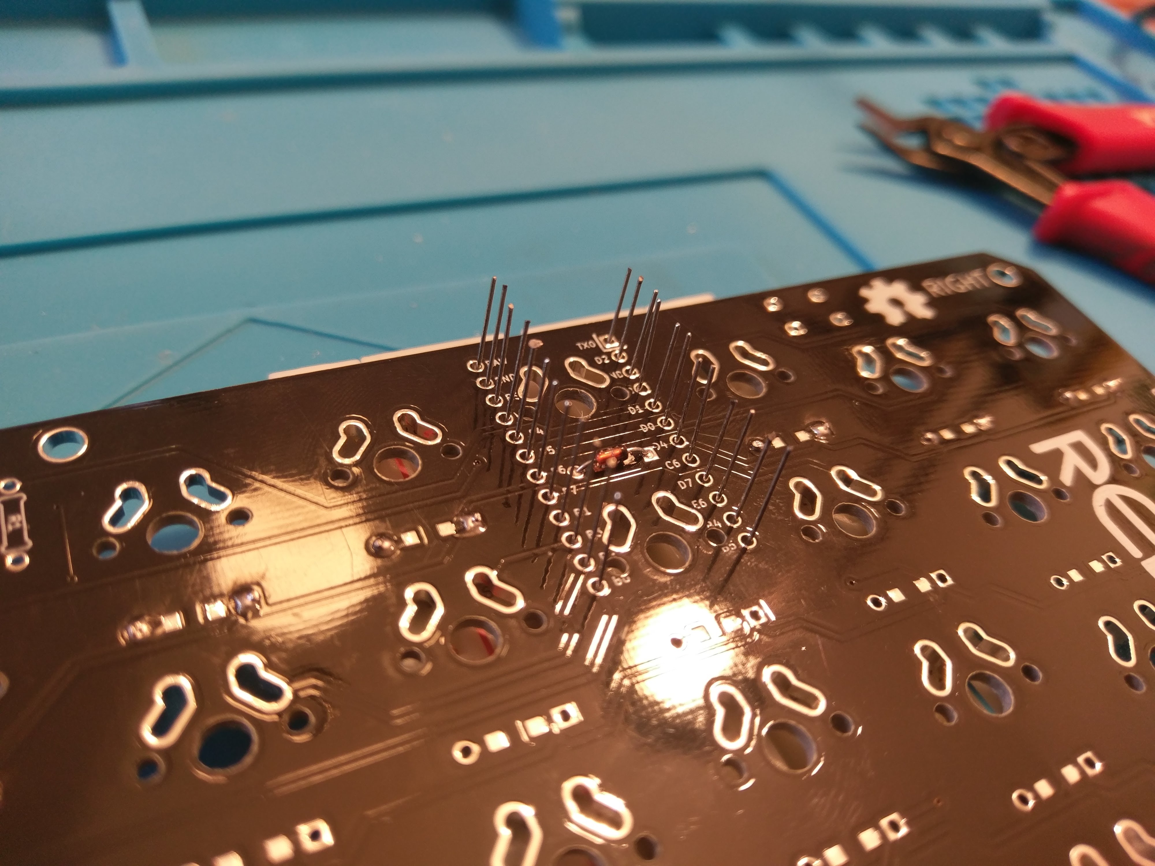
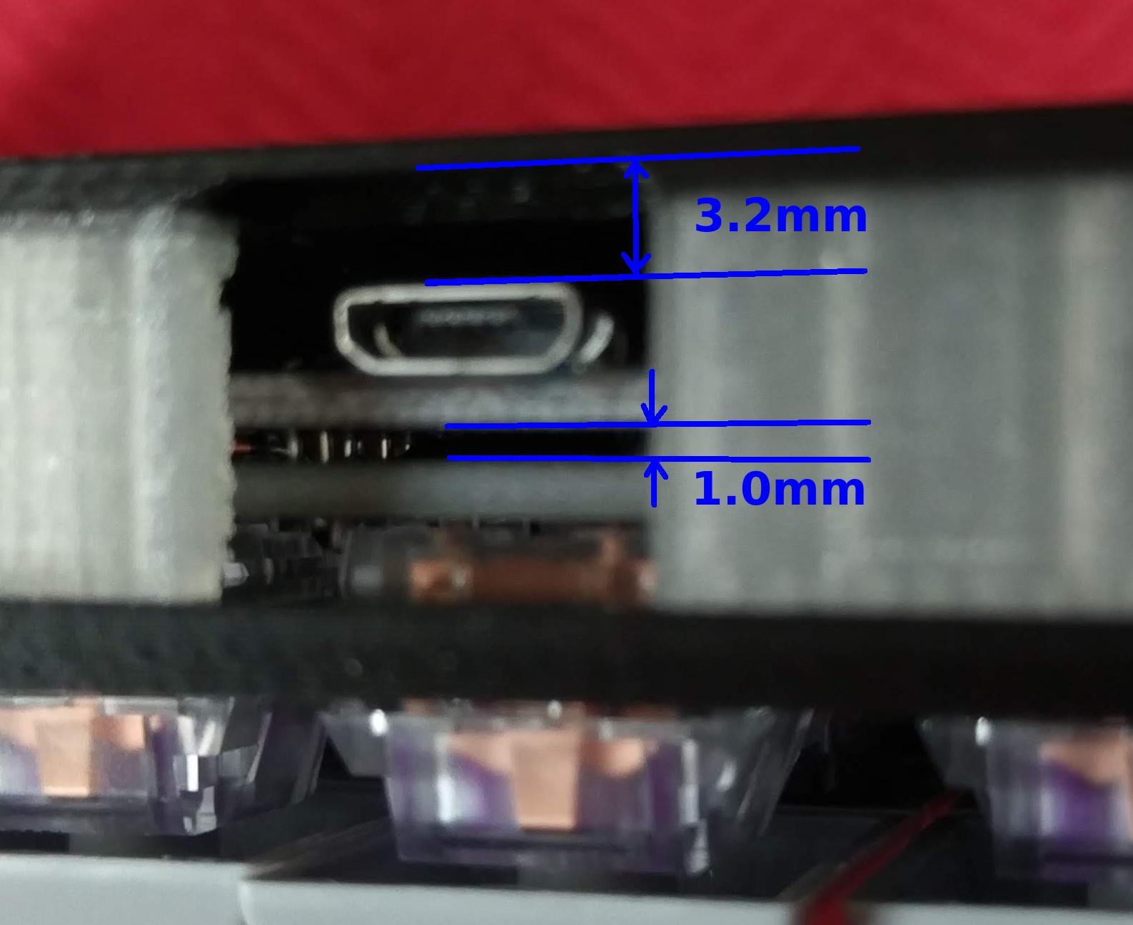
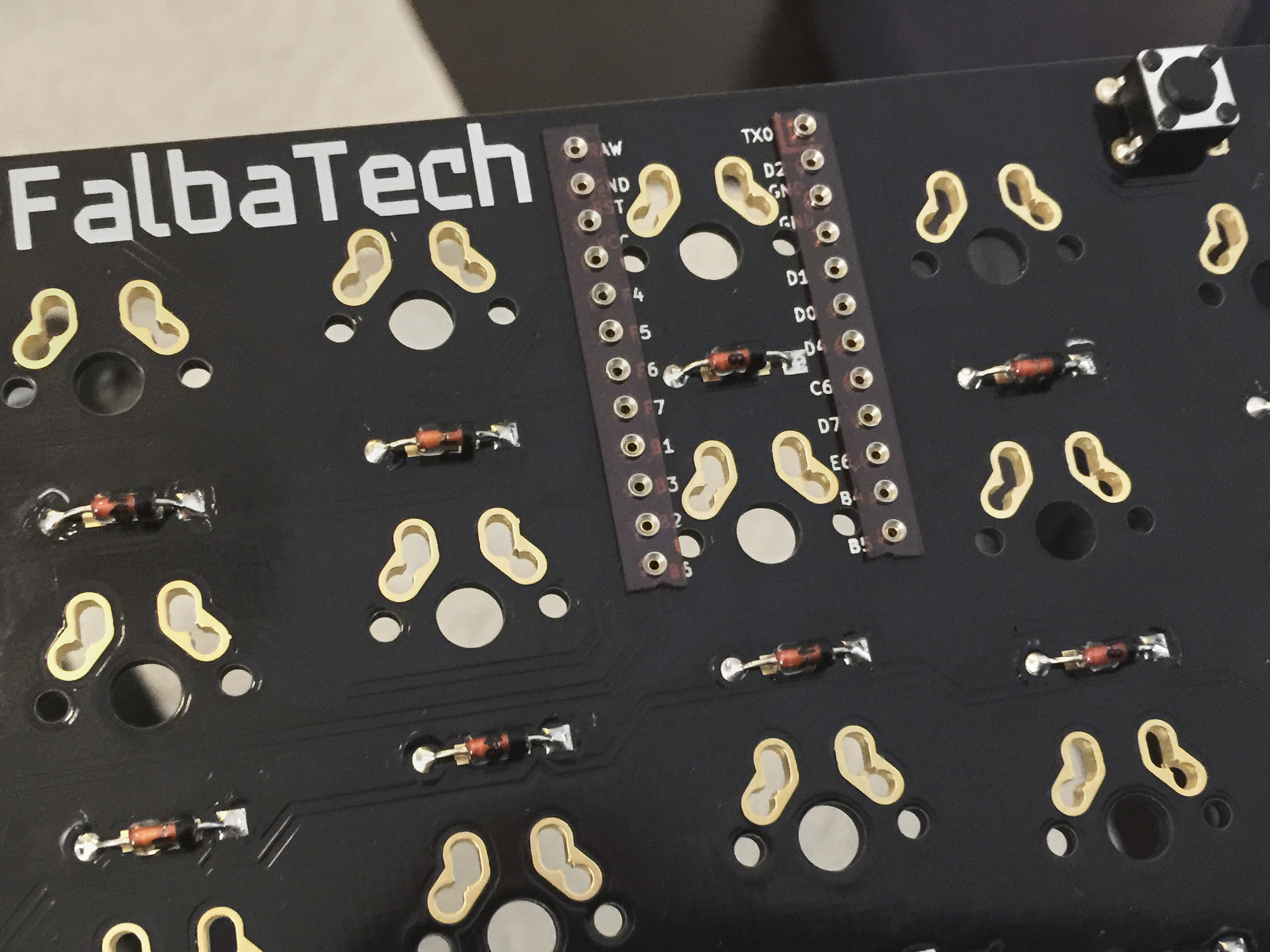
For the Pro Micro installation on the right hand use the diodes legs leftover from previous steps as this will make the controller's USB port much closer to the PCB, this is needed for the USB connector to fit in the 3D printed case. If you're using Falbatech's bamboo case this is not needed and you can use standard header pins. Right hand controller installation detail:
- Use a breadboard to keep the diode's legs from falling.
- Solder the diode's legs in place. You want to have the Pro Micro as close to the Redox's PCB as possible.
- Cut the excess.
- Apply some electrical tape under the controller to prevent shorts.
- Install your preferred switches (remember: the controller installation is the last step).
- Solder the controllers in place.
Here's some measurements of the Pro Micro installation:
If you're using Falbatech's bamboo case the use of the diode's legs is not needed and you can use standard header pins
⚠️ If you have a Redox with RGB backlight installed you MUST use the serial connection. For details see the RGB underglow firmware instructions.
The Redox uses QMK for its firmware, follow the QMK installation instructions here, then compile and burn the firmware on both halves as follows:
$ cd path/to/qmk_firmware
$ make redox/rev1:default:avrdude
After issuing this command you should see the following output:
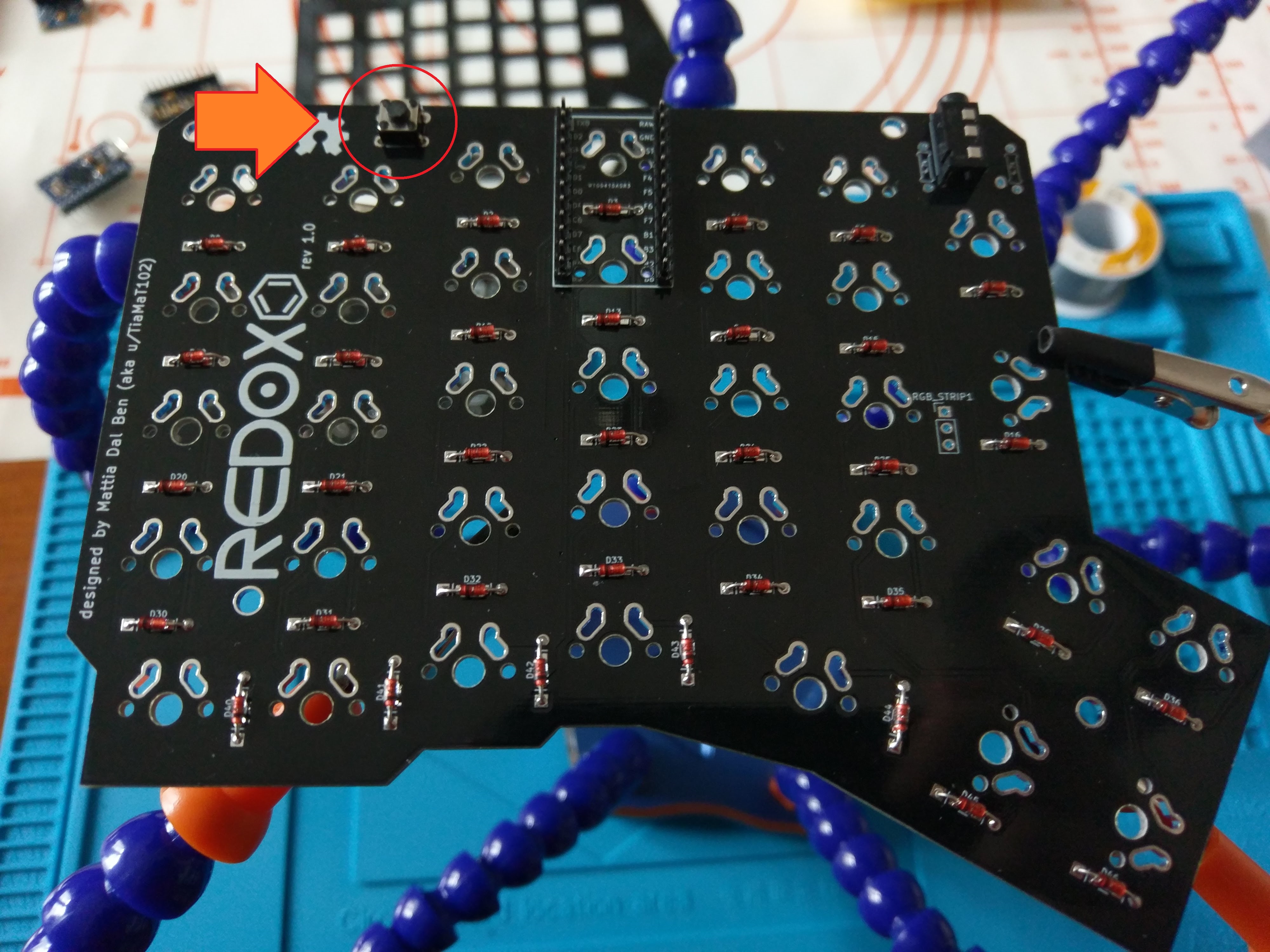
Detecting USB port, reset your controller now.....Now you should reset the Pro Micros using the reset button as seen in the following picture:
⚠️ You always need to burn the firmware on BOTH halves of the keyboard.
⚠️ Failing to upload Redox Firmware on Linux. Please refer to issue #8060 of QMK firmware.
You can find the code for the Redox here: QMK - Redox keyboard.
In the firmware/ folder I added some pre-built hex files with the default keymap for testing purpose. You can upload the firmware binaries directly using the command below:
avrdude -p atmega32u4 -P $(COM_PORT) -c avr109 -U flash:w:redox_rev1_default.hexIf you define EE_HANDS in your config.h, you will need to set the EEPROM for the left and right halves.
The EEPROM is used to store whether the half is left handed or right handed. This makes it so that the same firmware file will run on both hands instead of having to flash left and right handed versions of the firmware to each half. To flash the EEPROM file for the left half run:
$ cd path/to/qmk/folder
avrdude -p atmega32u4 -P $(COM_PORT) -c avr109 -U eeprom:w:"./quantum/split_common/eeprom-lefthand.eep"
// or the equivalent in dfu-programmer
and similarly for right half
avrdude -p atmega32u4 -P $(COM_PORT) -c avr109 -U eeprom:w:"./quantum/split_common/eeprom-righthand.eep"
// or the equivalent in dfu-programmer
⚠️ Replace$(COM_PORT)with the port of your device (e.g./dev/ttyACM0)
After you have flashed the EEPROM, you then need to set EE_HANDS in keyboard/redox/keymaps/default/config.h like so:
// ...
/* Use I2C or Serial, not both */

// #define USE_SERIAL
#define USE_I2C

/* Select hand configuration */

// #define MASTER_LEFT
// #define MASTER_RIGHT
#define EE_HANDS

#undef RGBLED_NUM
#define RGBLIGHT_ANIMATIONS
// ...
Then rebuild the hex files and reflash.
Note that you need to program both halves, but you have the option of using different keymaps for each half. You could program the left half with a QWERTY layout and the right half with a Colemak layout using bootmagic's default layout option. Then if you connect the left half to a computer by USB the keyboard will use QWERTY and Colemak when the right half is connected.
With a few modifications to the original design, it is possible to make a Redox with hot swappable switches and socketed Pro Micros. This was tested with Falbatech's PCBs and PVC cases. The switch hotswap mod should work with any case with a top plate that the switches snap into, with about a millimeter of extra clearance between the top plate and the PCB, and another extra half millimeter or so between the PCB and case bottom. If your (non-Falba) PCBs have particularly small diameter thru-holes for switch pins, check the Mill-Max 7305 spec sheet to ensure the receptacles will fit.
| Qty | Item | Notes |
|---|---|---|
| 1 | Peel-A-Way Sockets (82 pin strip) | Available from keeb.io |
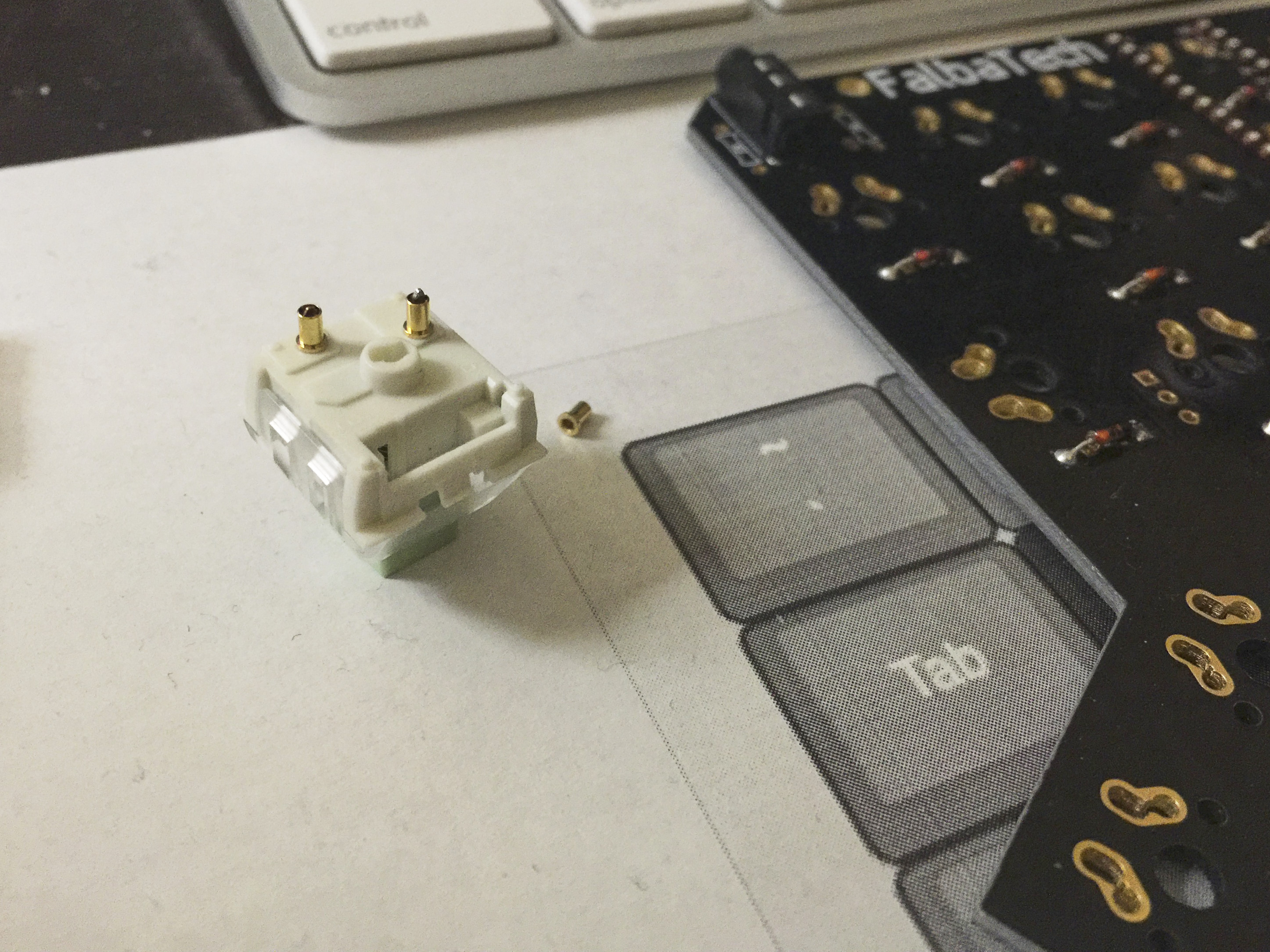
| 140 | Mill-Max 7305 Pin Receptacles | Available from Digi-Key or Mouser |
| 1 | Roll of Kapton tape |
Some extra Mill-Max receptacles may come in handy, in case of soldering mistakes or manufacturing defects.
Socketing your microcontrollers will allow you to swap out broken Pro Micros, or swap any Pro Micro pin-compatible microcontroller (with, for example, USB-C) into a finished build. Before you begin, you'll want to follow the standard assembly guide steps for soldering 1N4148 diodes, PJ-320A connectors, momentary switches, and any resistors you'll be using. Remember to trim the legs off your diodes and keep them, as we'll be using the legs to make pins for each Pro Micro.
Installation steps, after initial soldering:
- Using scissors or flush cutters, cut out two 12-pin strips of Peel-A-Way sockets.
- With the bottom side of the PCB (the side with the diodes, momentary switch, and TRRS connector visible) facing up, place the cut Peel-A-Way socket strips into the thru-holes where the Pro Micro headers would usually go.
- Temporarily fasten the Peel-A-Way sockets to the PCB with Kapton tape.
- Flip over the PCB.
- Solder the sockets into the thru-holes.
- Install your switches. This step differs depending on whether you plan
on making your switches hotswappable:
- For fixed, non-hotswap switches, follow the standard assembly guide.
- Hotswap switch builds should follow the hot swappable switch install guide.
- Flip and orient your Pro Micro so that its labels match the labels on your PCB, then cover the bottom of the Pro Micro in electrical or Kapton tape to prevent shorts.
- Thread the least bent of your trimmed diode legs through the thru-holes in your Pro Micro and into the corresponding sockets on the PCB.
- Keeping the Pro Micro as level as possible, solder the diode legs to the Pro Micro. It may help to keep a USB cable attached to the Pro Micro, to help ensure the port ends up in a usable orientation.
- Trim the excess length of the diode legs off of the top of the Pro Micro.
- Repeat these steps for the other half of your Redox.
⚠️ A few things to keep in mind:
- Some switch pins (so far, Kailh Box Royals) may be slighly too wide to fit the Mill-Max receptacle. When in doubt, try it with spare receptacles.
- The only thing keeping the PCB attached to the top plate is the switches; if you remove too many (more than half per side), the PCB will detach and fall into the case. Try to swap only a few switches at once.
To build a Redox with hot swappable switches, follow these steps instead of the switch installation instructions in the standard build guide. Soldering Mill-Max receptacles is trickier than soldering bare switch pins; a small iron tip, small diameter solder, and relatively low temperatures are recommended.
- Take each of your switches and push a Mill-Max receptacle fully onto each pin. One end of the receptacle has a small ring around it that makes it wider than the other end; the receptacle should be oriented so that the wide end is touching the switch housing (and will end up on the top, plate-facing side of the PCB in the assembled keyboard).
- Snap switches into each of the four corners of your top plate, and two more into the mounting holes that will be directly above the Pro Micro in the assembled keyboard.
- Flip over the top plate and install the PCB.
- The receptacles might be a tight fit for the PCB thru-holes; if so, press the PCB into the switches to make sure the PCB is fully mounted and level.
- Install the rest of the switches, starting from the outside edges of the
plate and moving inward.
- Initially, installing switches will likely shift the surrounding unsoldered switches and the PCB out of position, so pinch any jostled switches and the PCB back together as you go.
- Be careful not to apply too much pressure to the stem of the switch, as this could damage it.
- Solder your switches, starting from the corners then going from the outside
edges to the inner switches in roughly the same order as the previous step.
- Before soldering each switch, apply pressure to the top of the switch and the bottom of the PCB a final time to ensure the switch, plate, and PCB are all properly seated.
- Apply heat to the pin receptacle and pad, then melt your solder onto the pad. You will want a "volcano" shaped solder joint which fully encircles the bottom of the receptacle, but doesn't fill its inner surface.
- If you need to test that you haven't accidentally soldered a pin permanently into its receptacle by allowing solder to spill into the inner surface of the receptacle, you can try and temporarily remove the switch as you would during a hot swap. Use a switch puller to depress the tabs on the top and bottom of the switch (or the left and right for the flipped 1.5u key switches), and gently pull up on the switch until it is free of the keyboard. Note that if the switch and receptacles are still hot, it might take some extra effort to pull out the switch. Next, snap the switch back into its socket, and fix any unsoldered switches that were knocked out of place during this process.
- Repeat these steps for the other side of the keyboard.
⚠️ With this configuration:
- You don't need to solder the 4.7k resistors since the I2C connection won't be used.
- You can use only one hand as master.
Parts:
- WS2812/WS2812B LED strip
- 24 AWG (or smaller) stranded wire (white, red, black are good choices)
Data connection:
Led strip Headers -> DIN -> DO -> TRRS pad -> (TRRS to other side) -> TRRS pad -> DIN
- On the LEFT hand:
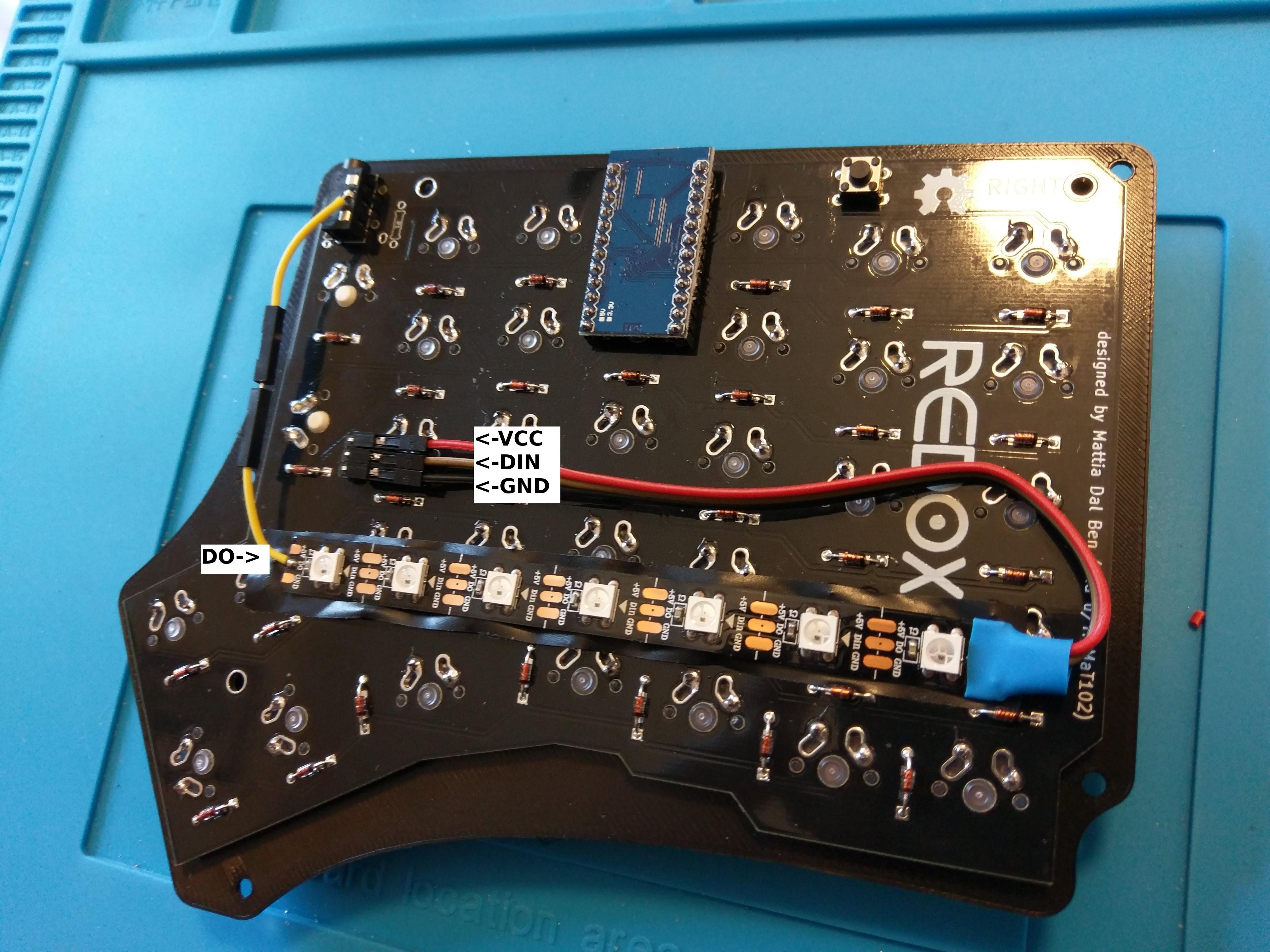
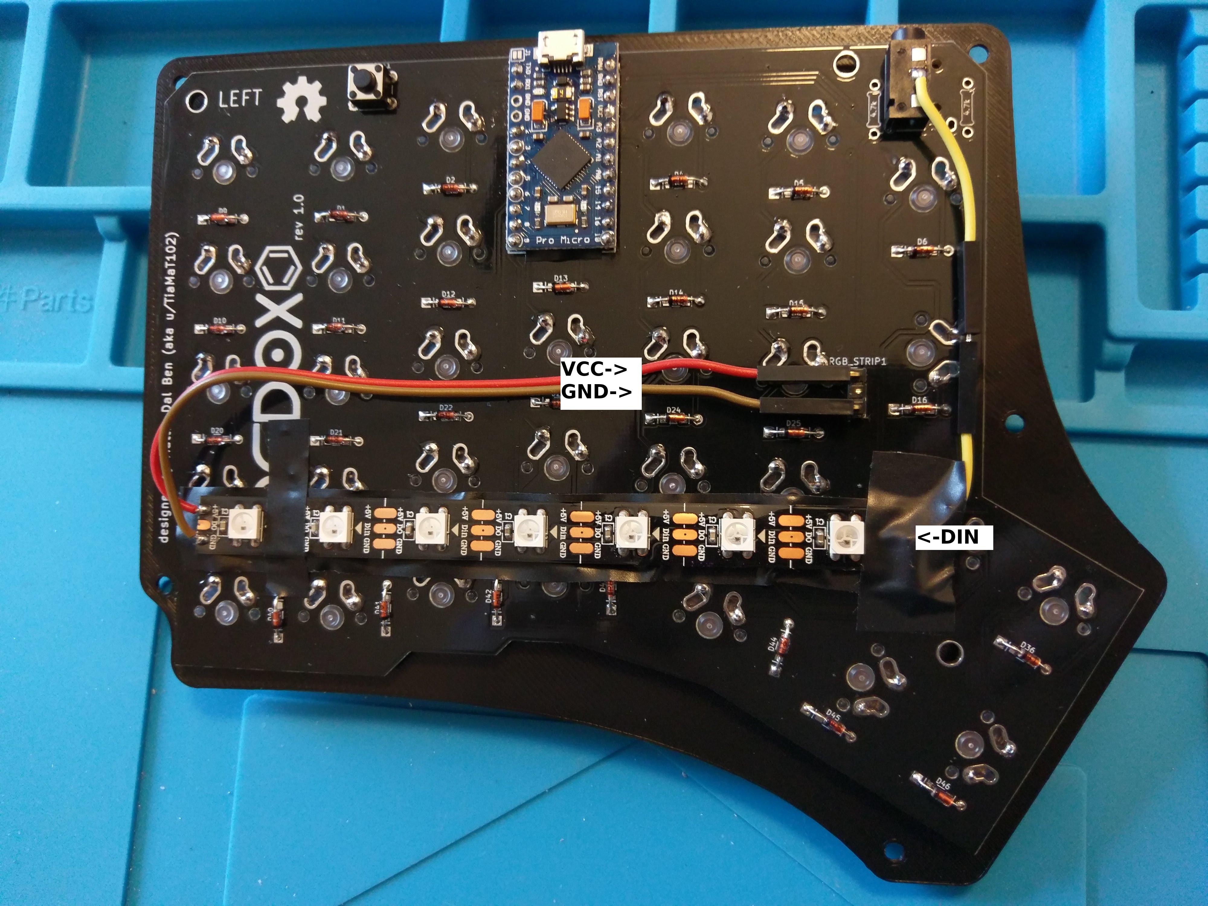
- Solder the LED Strip headers as seen in the pictures below.
- Solder the DO Pin of the RGB strip to the TRRS pad as seen in the figures below.
- On the RIGHT hand:
- Solder VCC and GND of the RGB strip to the LED Strip headers.
- Solder the DIN Pin of the RGB strip to the TRRS pad as seen in the figures below.
- Flash the firmware with the serial and RGB Backlight options on, specifying the number of LEDs installed (see instruction here).
- On the RIGHT hand:
- Solder the LED Strip headers to the RGB strip.
- Solder the DO Pin of the RGB strip to the TRRS pad.
- On the LEFT hand:
- Solder VCC and GND of the RGB strip to the LED Strip headers.
- Solder the DIN Pin of the RGB strip to the TRRS pad.
To enable RGB backlighting you need to modify the default firmware as follows:
- Use serial communication instead of I2C.
- Set the master hand.
- Set the number of LED you installed.
To do this, modify qmk_firmware/keyboards/redox/keymaps/default/config.h as follows:
// ...

/* You need to use the sarial communication since we
used a cable to carry the data signal for the LED strip */
#define USE_SERIAL

/* Select hand configuration: you need to use as master
the hand that drives the LED strip */
#define MASTER_LEFT
// #define MASTER_RIGHT

/* Put the total number of led used here */
#undef RGBLED_NUM
#define RGBLIGHT_ANIMATIONS
#define RGBLED_NUM 14
#define RGBLIGHT_HUE_STEP 8
#define RGBLIGHT_SAT_STEP 8
#define RGBLIGHT_VAL_STEP 8

// ...
Then compile and burn the firmware on both controllers:
$ cd path/to/qmk_firmware
$ make redox/rev1:default:avrdude


