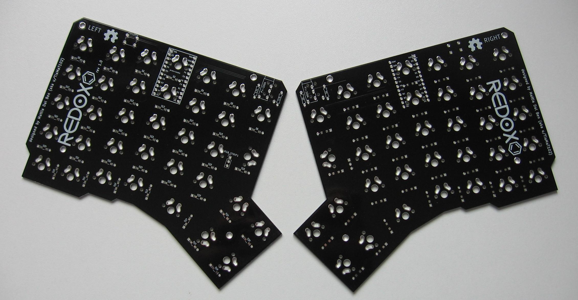
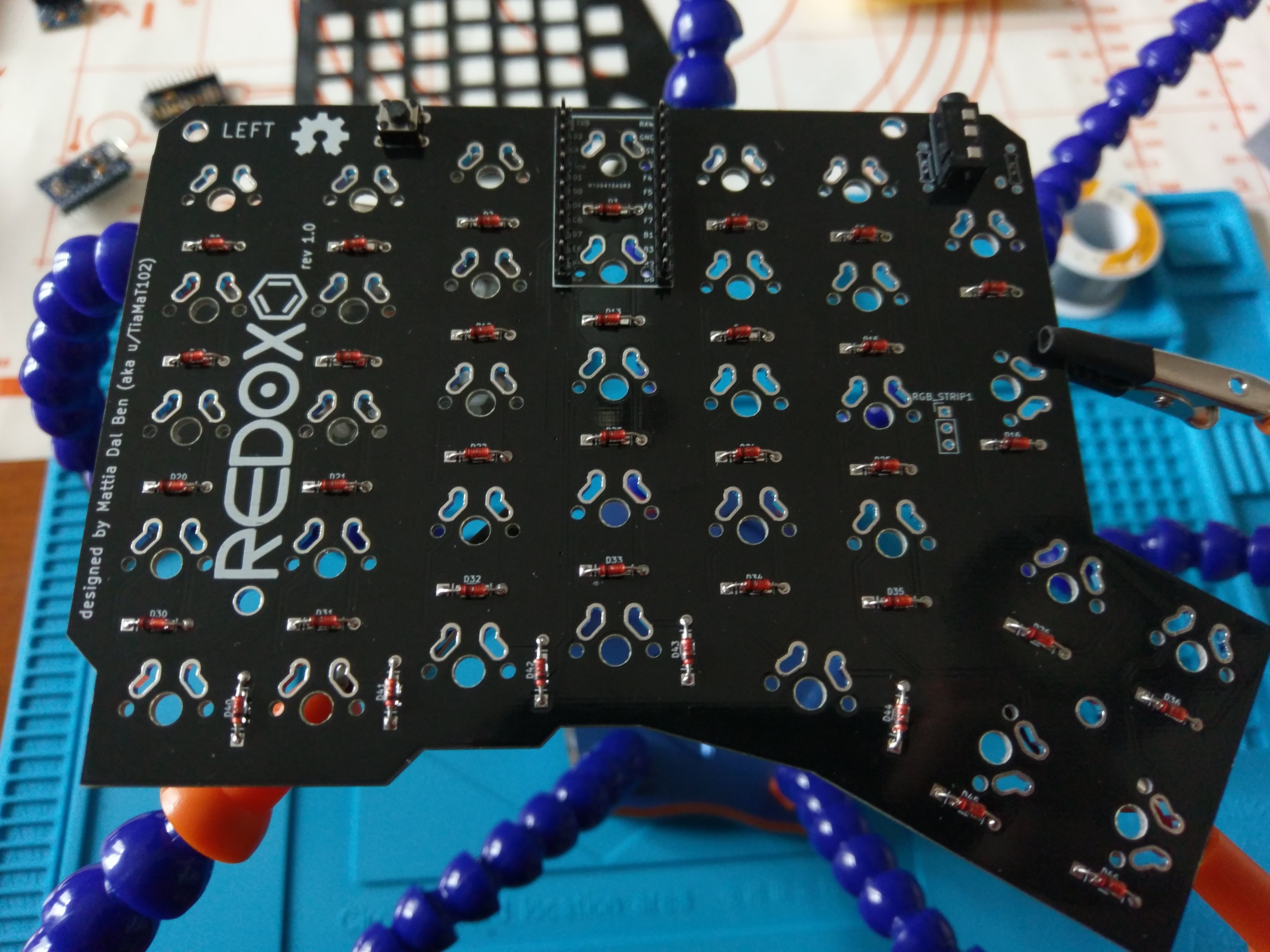
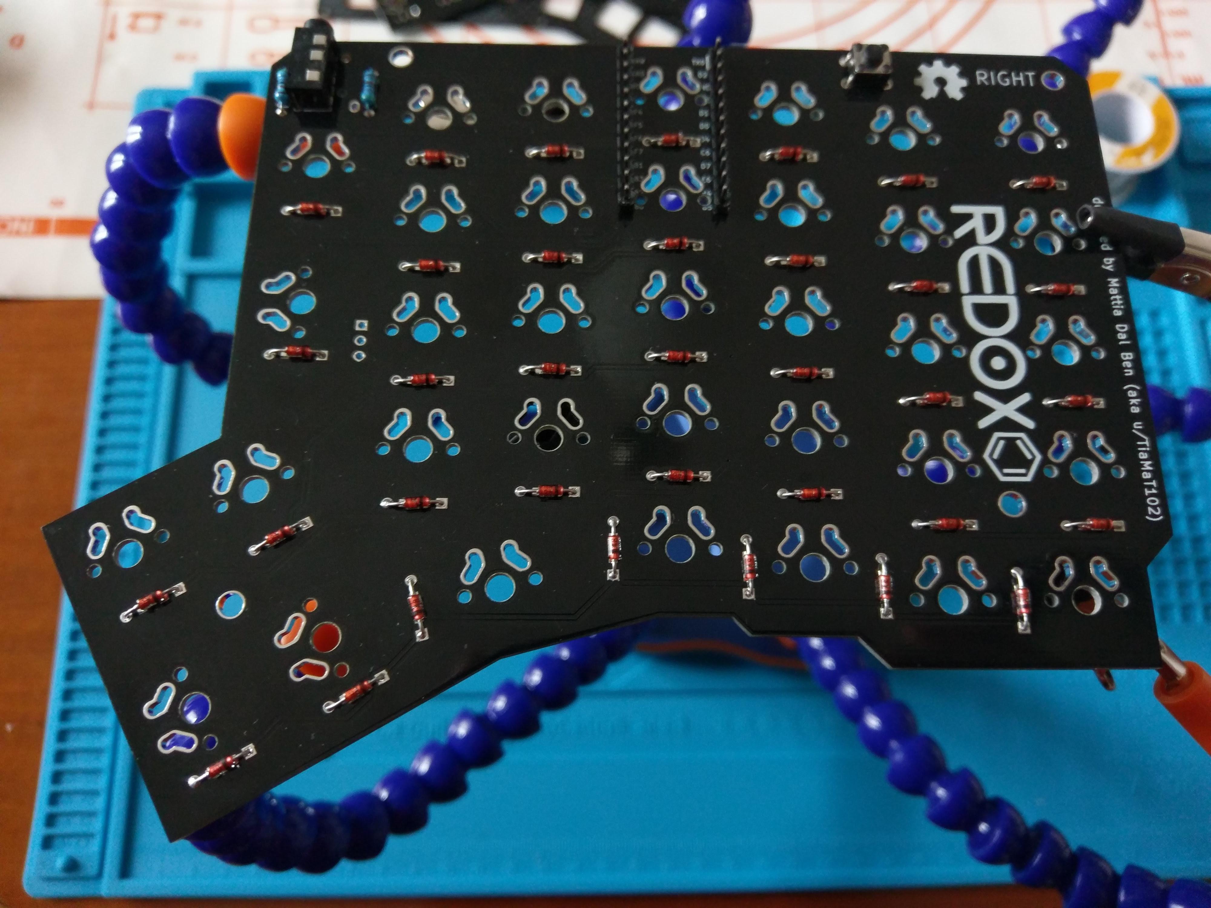
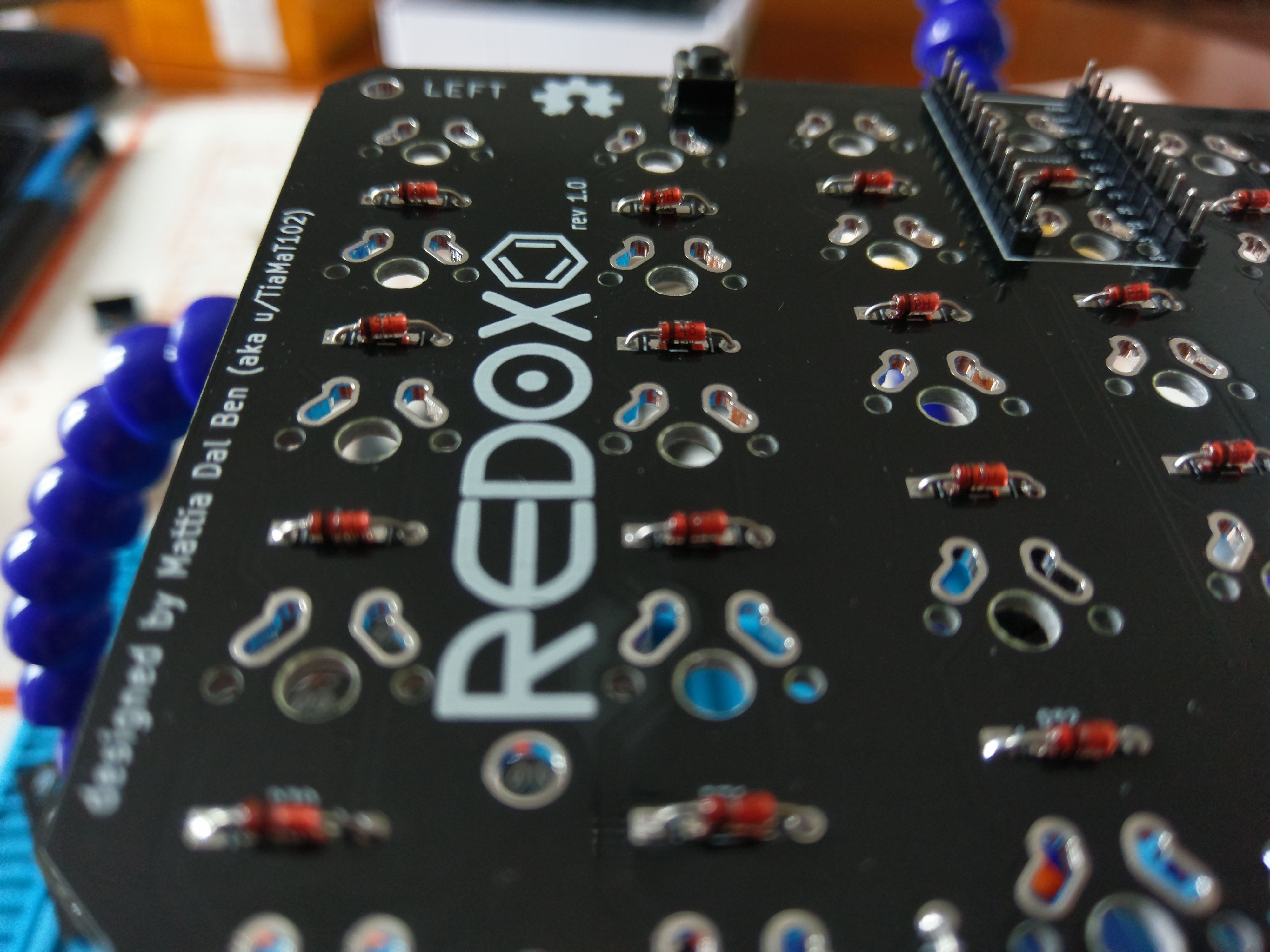
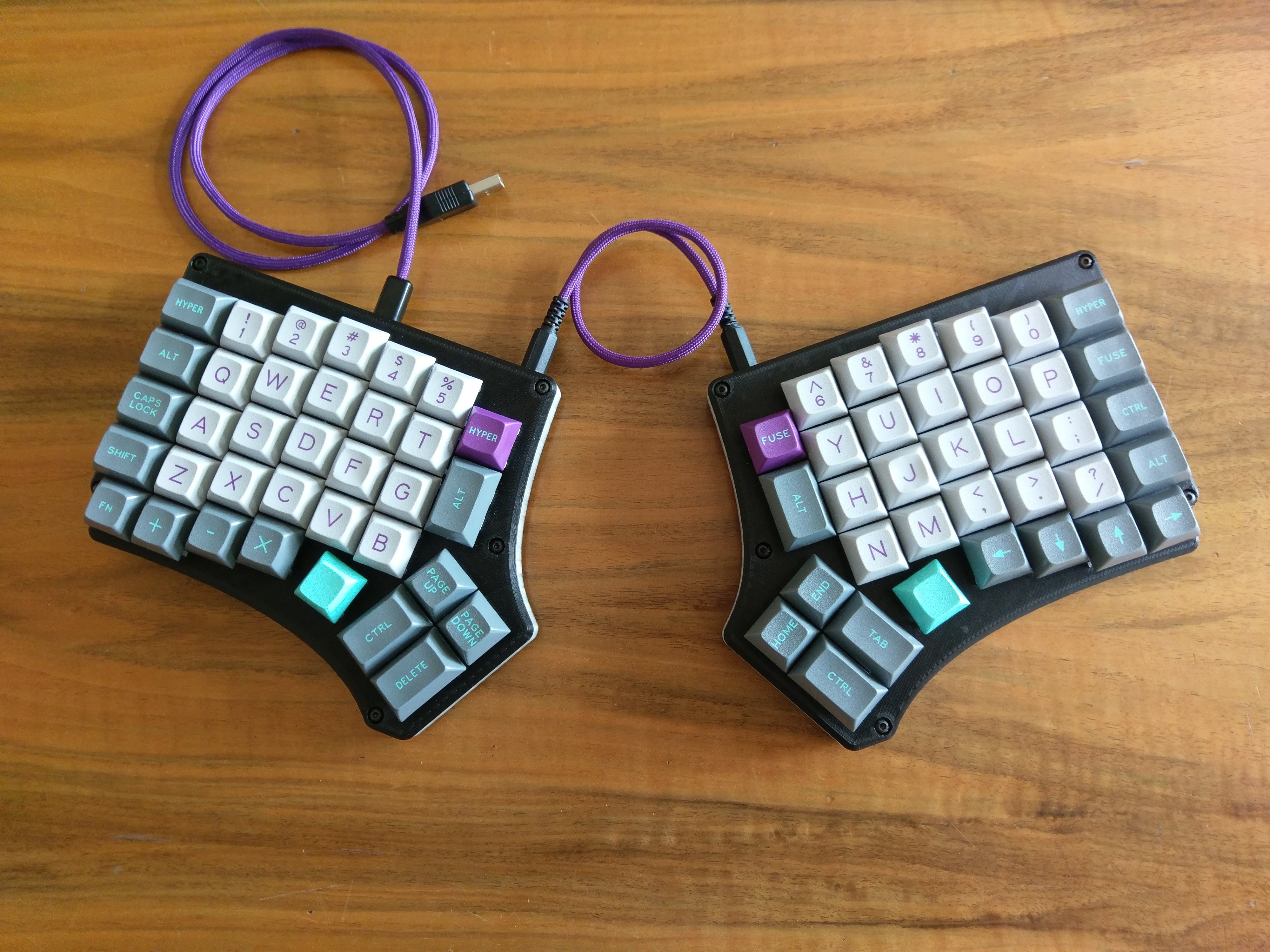
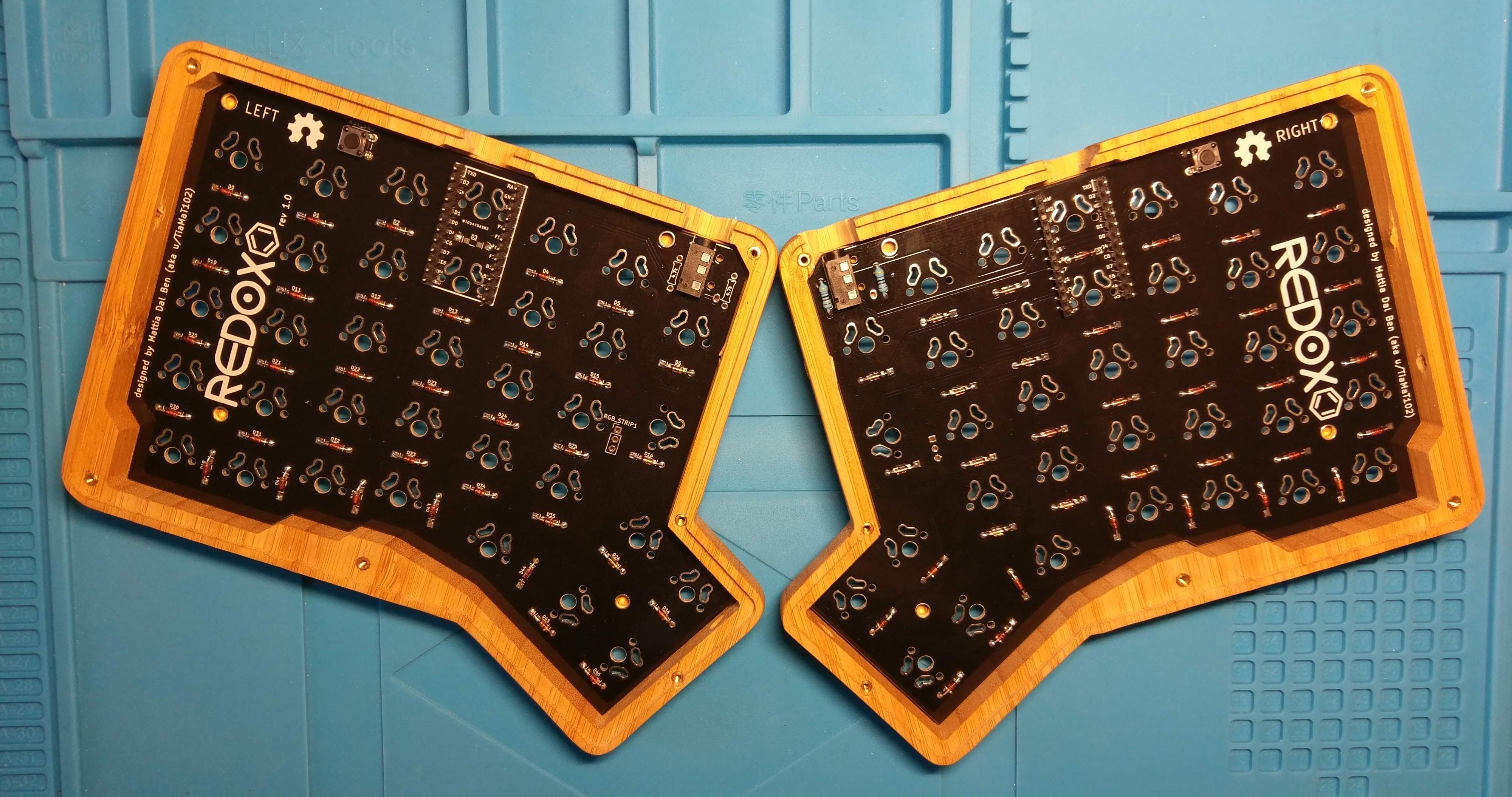
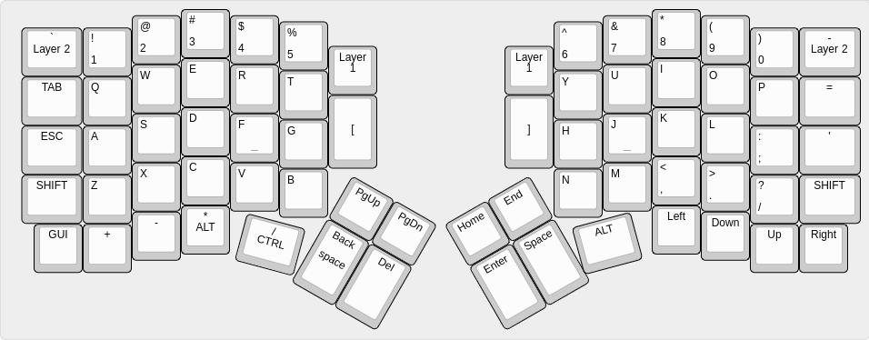
The Redox rev.1 is the first commercially available version of the Redox keyboard.
Hardware availability:
| Qty | Item | Notes |
|---|---|---|
| 70 | Cherry MX compatible switches | |
| 2 | Redox PCBs | Availalble here |
| 70 | 1N4148 diodes | SMD diodes can also be used |
| 2 | PJ-320A 4 poles 3.5 mm TRRS connectors | |
| 2 | 4.7 kOhm resistors | Need to be soldered on one half only |
| 2 | Through hole momentary switch | Dimensions 6mm x 6mm x 4.3mm |
| 2 | Arduino Pro Micro compatible microcontrollers | |
| 1 | TRRS cable | |
| 1 | USB micro cable | |
| 70 | Cherry MX compatible keycaps | 10x 1.25u keycaps, 6x 1.5u keycaps, 54x 1u keycaps |
| 14 | WS2812/WS2812B leds | Optional RGB-underglow |
External links to some other guides to building the Redox keyboard:
- "Build your own keyboard" by @costask.
- Imgur build log (3D printed case).
Installation steps:
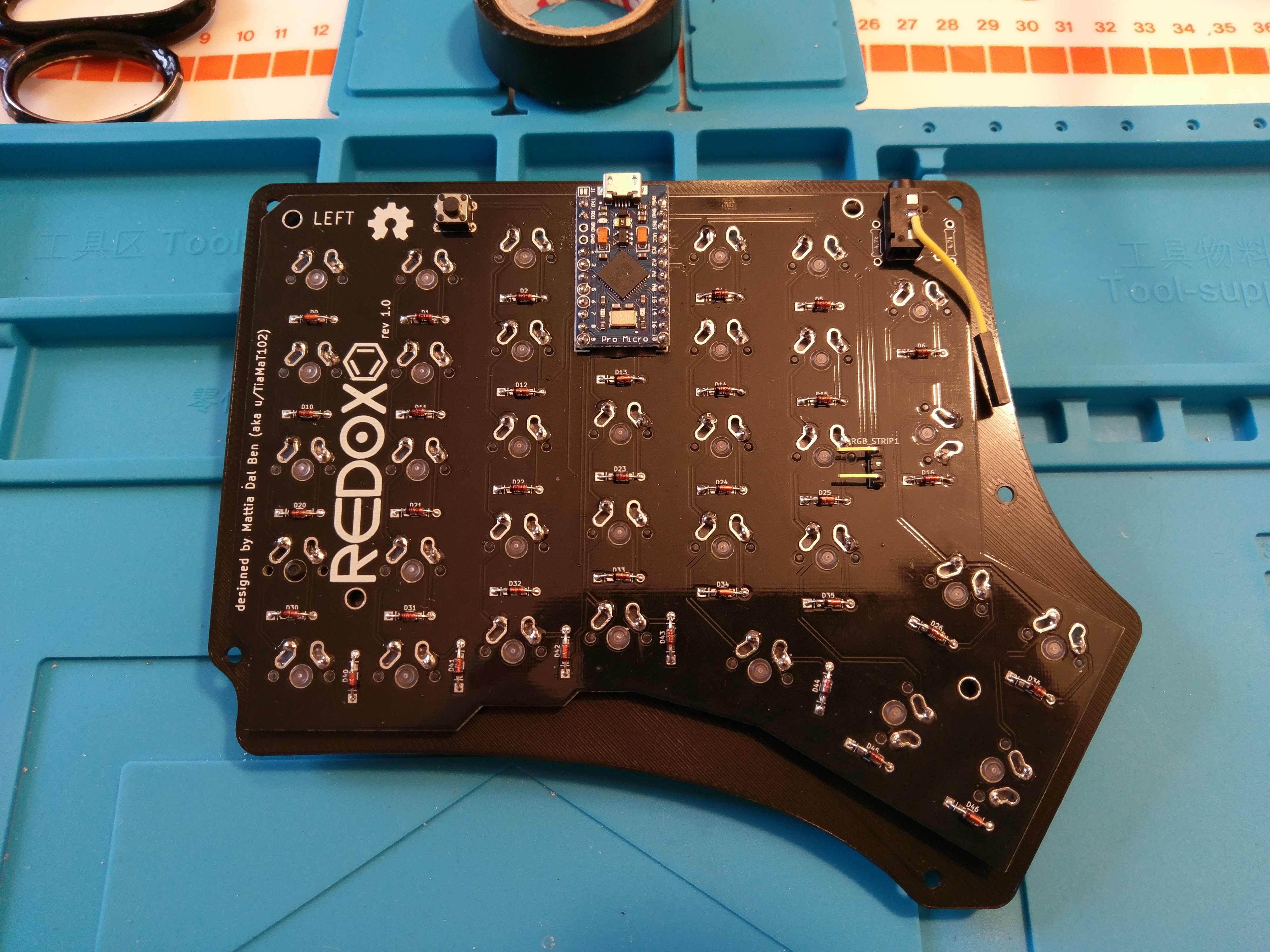
- Solder components:
- Solder 1N4148 diodes. Keep the diode legs for the right hand controller installation.
- Solder PJ-320A connectors.
- Solder momentary switches.
- Solder 4.7k Ohm resistors on one half only. If you are going for the RGB-underglow ignore this step.
- Solder the Pro Micro header pins (do not solder the Pro Micro controllers yet). This step may differ depending on which case your're using. Refer to the following:
- See 3D-Printed case right hand controller installation detail.
- See Falbatech's bamboo case.
- Optional see RGB-underglow instructions.
- Flip the PCBs.
- Solder switches to the PCB.
- Flip the PCBs again.
- Solder Pro Micros to the header pins following the PCB labelling.
To lower the build costs I designed a 3D printable case which you can find in this repository or on thingiverse, feel free to modify it to best suit your needs.
Parts:
| Qty | Item | Notes |
|---|---|---|
| 1 | Left top plate | RedoxRev1TopLeft.STL |
| 1 | Left bottom | RedoxRev1BottomLeft.STL |
| 1 | Right top plate | RedoxRev1TopRight.STL |
| 1 | Right bottom | RedoxRev1BottomRight.STL |
| 10 | M3 x 8mm (or 5mm) screws |
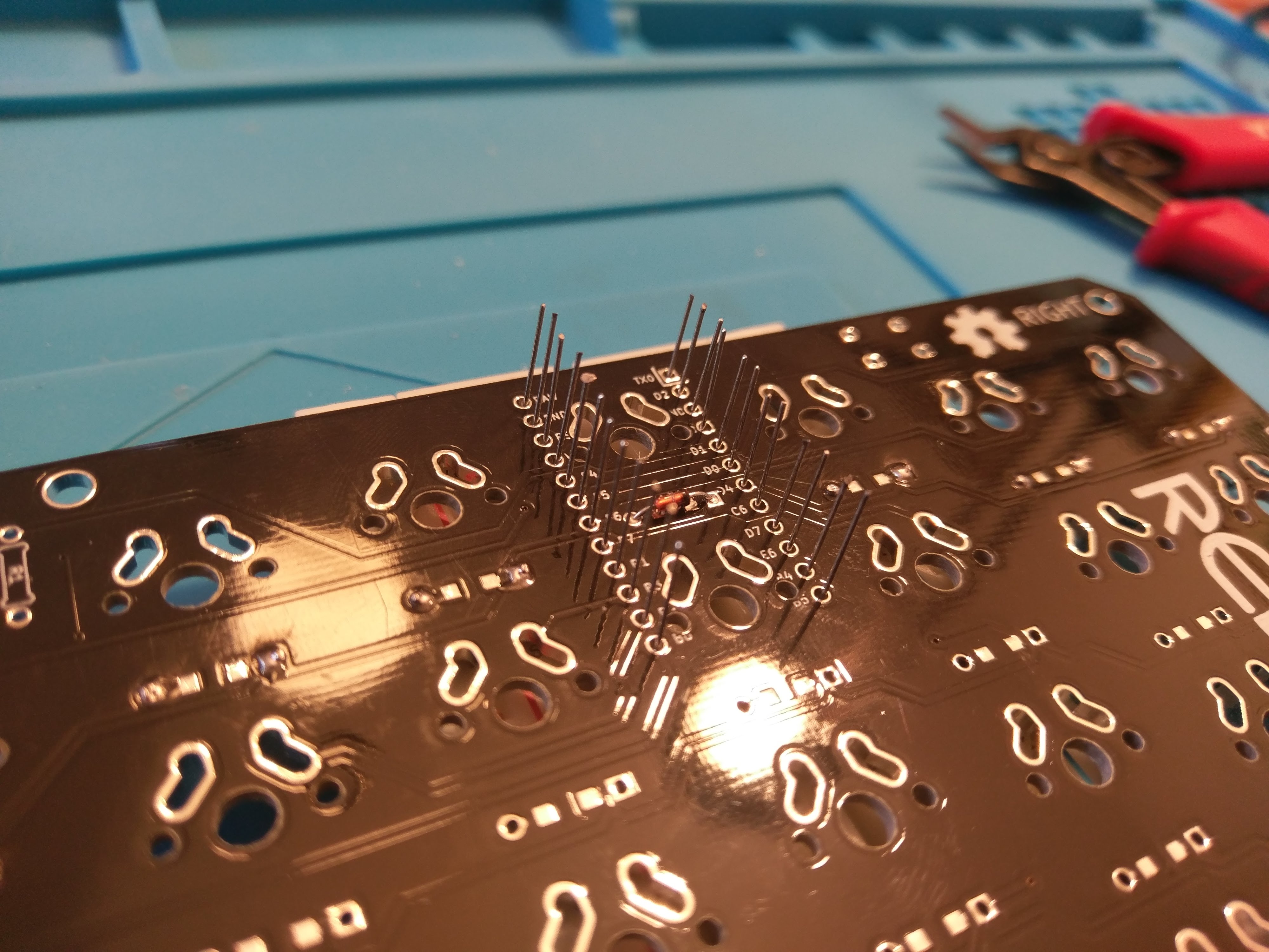
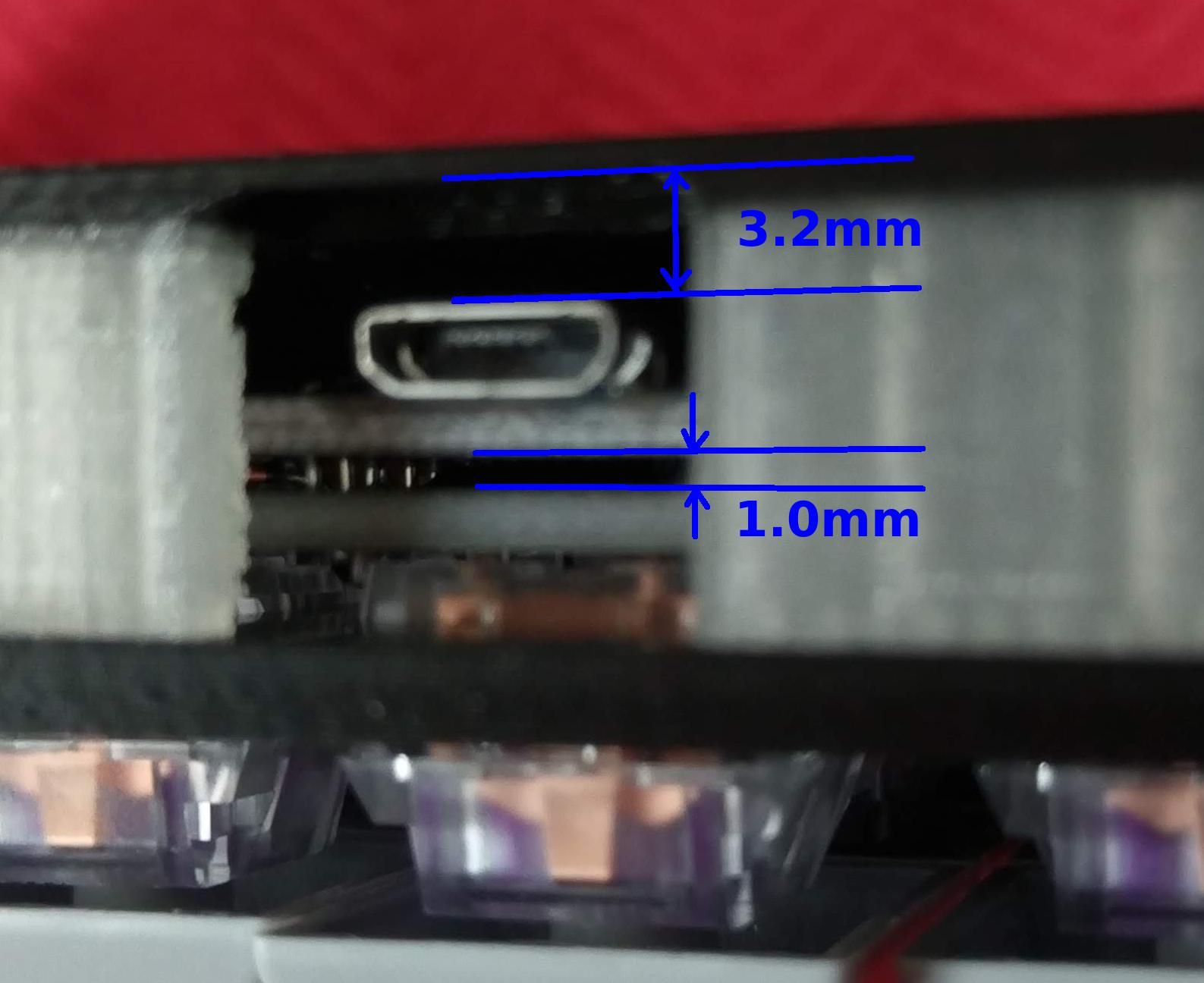
For the Pro Micro installation on the right hand use the diodes legs leftover from previous steps as this will make the controller's USB port much closer to the PCB, this is needed for the USB connector to fit in the 3D printed case. If you're using Falbatech's bamboo case this is not needed and you can use standard header pins. Right hand controller installation detail:
- Use a breadboard to keep the diode's legs from falling.
- Solder the diode's legs in place. You want to have the Pro Micro as close to the Redox's PCB as possible.
- Cut the excess.
- Apply some electrical tape under the controller to prevent shorts.
- Install your preferred switches (remember: the controller installation is the last step).
- Solder the controllers in place.
Here's some measurements of the Pro Micro installation:
If you're using Falbatech's bamboo case the use of the diode's legs is not needed and you can use standard header pins
⚠️ If you have a Redox with RGB backlight installed you MUST use the serial connection. For details see the RGB underglow firmare instructions.
The Redox uses QMK for its firmware, follow the QMK installation instructions here, then compile and burn the firmware on both halves as follows:
$ cd path/to/qmk_firmware
$ make redox/rev1:default:avrdude
⚠️ You always need to burn the firmware on BOTH halves of the keyboard.
You can find the code for the Redox here: QMK - Redox keyboard.
In the firmware/ folder I added some pre-built hex files with the default keymap for testing purpose. You can upload the firmware binaries directly using the command below:
avrdude -p atmega32u4 -P $(COM_PORT) -c avr109 -U flash:w:redox_rev1_default.hexIf you define EE_HANDS in your config.h, you will need to set the EEPROM for the left and right halves.
The EEPROM is used to store whether the half is left handed or right handed. This makes it so that the same firmware file will run on both hands instead of having to flash left and right handed versions of the firmware to each half. To flash the EEPROM file for the left half run:
$ cd path/to/qmk/folder
$ avrdude -p atmega32u4 -P $(COM_PORT) -c avr109 -U eeprom:w:keyboards/lets_split/eeprom-lefthand.eep
and similarly for right half
$ avrdude -p atmega32u4 -P $(COM_PORT) -c avr109 -U eeprom:w:keyboards/lets_split/eeprom-righthand.eep
⚠️ Replace$(COM_PORT)with the port of your device (e.g./dev/ttyACM0)
After you have flashed the EEPROM, you then need to set EE_HANDS in keyboard/redox/keymaps/default/config.h like so:
// ...
/* Use I2C or Serial, not both */

// #define USE_SERIAL
#define USE_I2C

/* Select hand configuration */

// #define MASTER_LEFT
// #define MASTER_RIGHT
#define EE_HANDS

#undef RGBLED_NUM
#define RGBLIGHT_ANIMATIONS
// ...
⚠️ With this configuration:
- You don't need to solder the 4.7k resistors since the I2C connection won't be used.
- You can use only one hand as master.
Parts:
- WS2812/WS2812B LED strip
- 24 AWG (or smaller) stranded wire (white, red, black are good choices)
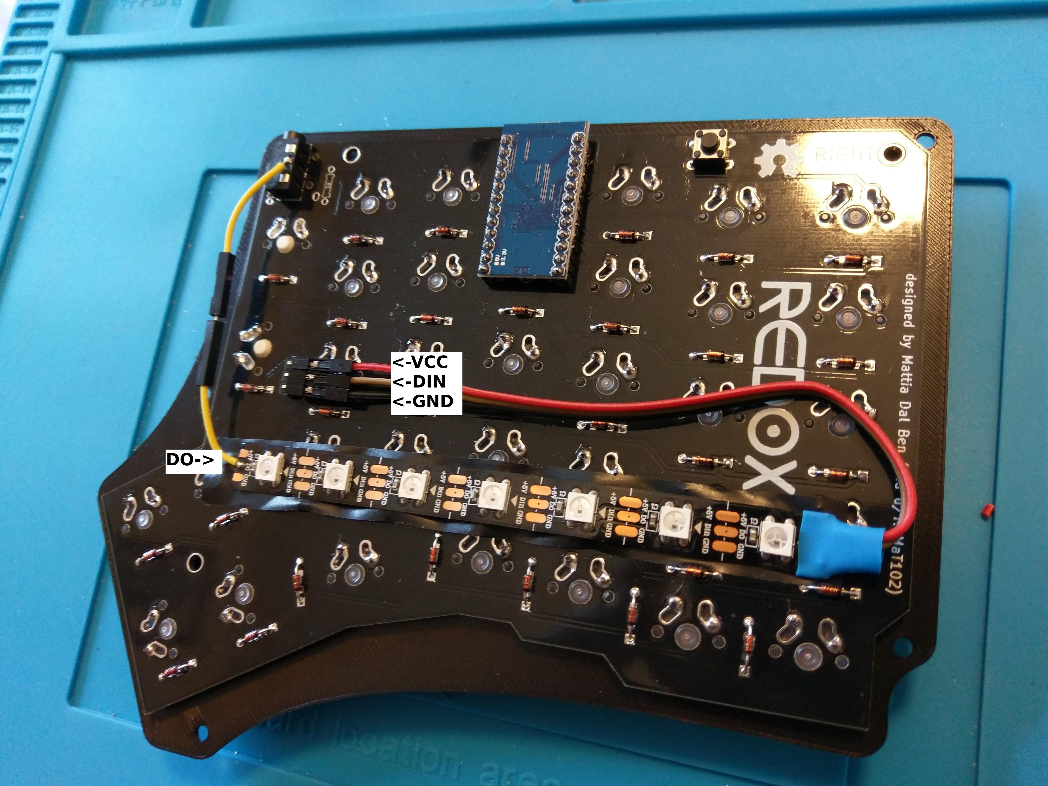
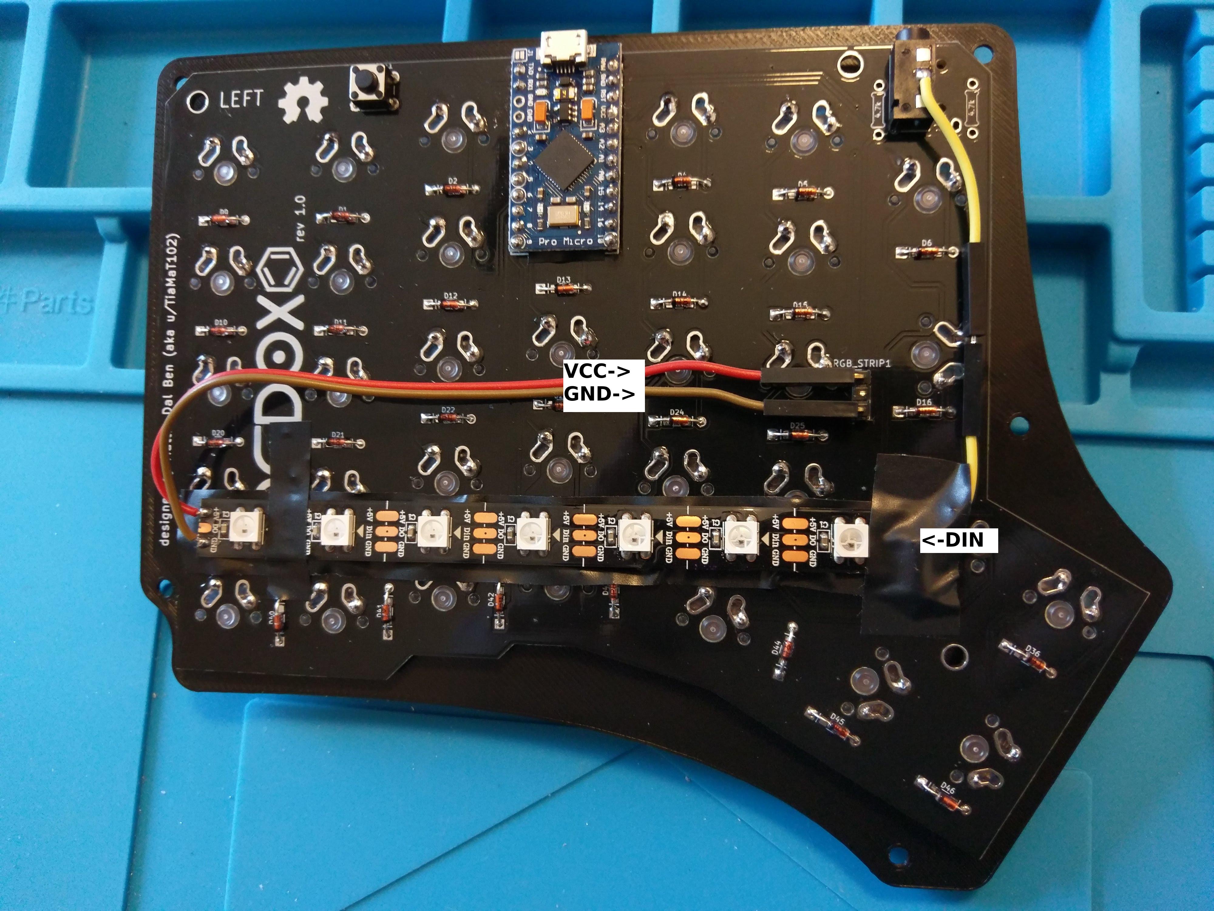
Data connection:
Led strip Headers -> DIN -> DO -> TRRS pad -> (TRRS to other side) -> TRRS pad -> DIN
- On the LEFT hand:
- Solder the LED Strip headers as seen in the pictures below.
- Solder the DO Pin of the RGB strip to the TRRS pad as seen in the figures below.
- On the RIGHT hand:
- Solder VCC and GND of the RGB strip to the LED Strip headers.
- Solder the DIN Pin of the RGB strip to the TRRS pad as seen in the figures below.
- Flash the firmware with the serial and RGB Backlight options on, specifying the number of LEDs installed (see instruction here).
- On the RIGHT hand:
- Solder the LED Strip headers to the RGB strip.
- Solder the DO Pin of the RGB strip to the TRRS pad.
- On the LEFT hand:
- Solder VCC and GND of the RGB strip to the LED Strip headers.
- Solder the DIN Pin of the RGB strip to the TRRS pad.
To enable RGB backlighting you need to modify the default firmware as follows:
- Use serial communication instead of I2C.
- Set the master hand.
- Set the number of LED you installed.
To do this, modify qmk_firmware/keyboards/redox/keymaps/default/config.h as follows:
// ...

/* You need to use the sarial communication since we
used a cable to carry the data signal for the LED strip */
#define USE_SERIAL

/* Select hand configuration: you need to use as master
the hand that drives the LED strip */
#define MASTER_LEFT
// #define MASTER_RIGHT

/* Put the total number of led used here */
#undef RGBLED_NUM
#define RGBLIGHT_ANIMATIONS
#define RGBLED_NUM 14
#define RGBLIGHT_HUE_STEP 8
#define RGBLIGHT_SAT_STEP 8
#define RGBLIGHT_VAL_STEP 8

// ...
Then compile and burn the firmware on both controllers:
$ cd path/to/qmk_firmware
$ make redox/rev1:default:avrdude