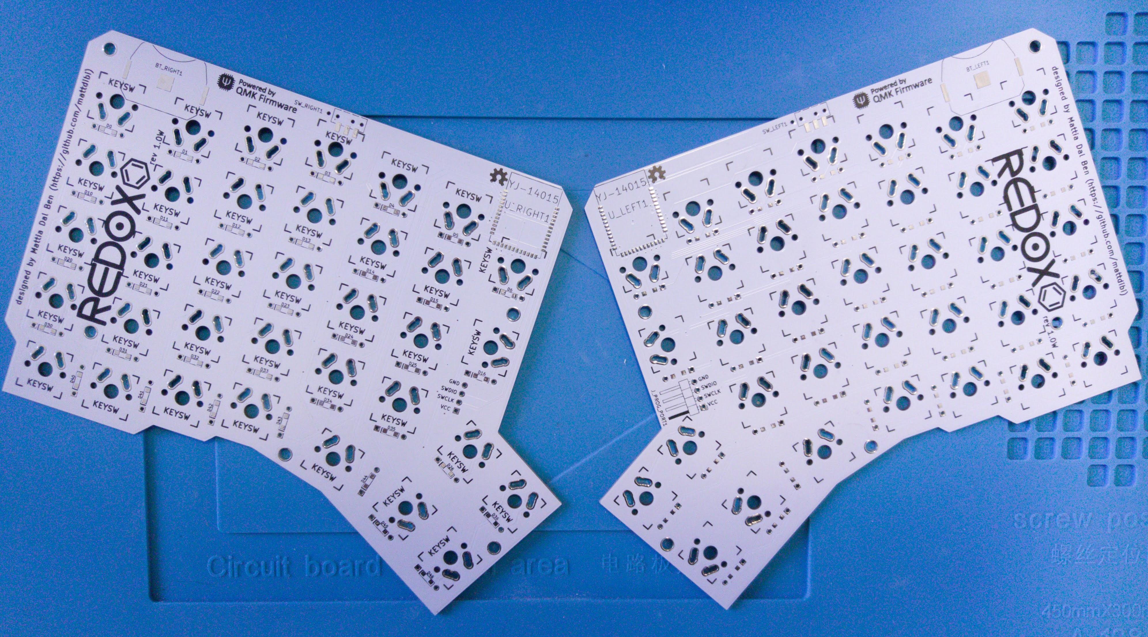
## Redox Wireless (a.k.a. codename Ultron)
The Redox Wireless is the wireless version of the Redox keyboard.
Hardware availability:
- [Falbatech](https://falba.tech/)
## Summary
- [Bill of materials](#bill-of-materials)
- [Transmitters Assembly](#transmitters-assembly)
- [Receiver Assembly](#receiver-assembly)
- [Firmware](#firmware)
- [Battery usage](#battery-usage)
## Bill of materials
#### Transmitters
| Qty | Item | Notes |
|----:|-----------------------------------------------|-----------------------------------------------------|
| 70 | Cherry MX compatible switches | |
| 2 | Redox Wireless PCBs | |
| 2 | YJ-14015 modules (Core51822B clones) | [aliexpress](https://www.aliexpress.com/item/NRF51822-Core51822-BLE-4-0-Bluetooth-2-4G-Wireless-Module-Antenna-Board-For-ULP-SPI-I2C/32842154172.html?spm=2114.search0104.3.8.663a616aYeRlVr&ws_ab_test=searchweb0_0,searchweb201602_1_10065_10068_10843_10059_10884_10887_10696_100031_10084_10083_10103_10618_10304_10307_10820_10821_10302,searchweb201603_60,ppcSwitch_5&algo_expid=1dded059-5054-4890-bcc4-6face1150a21-1&algo_pvid=1dded059-5054-4890-bcc4-6face1150a21&priceBeautifyAB=0)
| 70 | 1N4148 diodes | SMD diodes can also be used |
| 2 | Keystone 3034 SMT battery holders | [digikey](https://www.digikey.com/product-detail/en/keystone-electronics/3034/36-3034-ND/4499289)|
| 2 | JS102011SAQN SMT slide switch | [digikey](https://www.digikey.com/product-detail/en/c-k/JS102011SAQN/401-1999-1-ND/1640114)|
| 2 | Right angle 0.1" header (1x4pin) | |
#### Receiver
| Qty | Item | Notes |
|----:|-----------------------------------------------|-----------------------------------------------------|
| 1 | Redox receiver PCB | |
| 1 | YJ-14015 module (Core51822B clone) | [aliexpress](https://www.aliexpress.com/item/NRF51822-Core51822-BLE-4-0-Bluetooth-2-4G-Wireless-Module-Antenna-Board-For-ULP-SPI-I2C/32842154172.html?spm=2114.search0104.3.8.663a616aYeRlVr&ws_ab_test=searchweb0_0,searchweb201602_1_10065_10068_10843_10059_10884_10887_10696_100031_10084_10083_10103_10618_10304_10307_10820_10821_10302,searchweb201603_60,ppcSwitch_5&algo_expid=1dded059-5054-4890-bcc4-6face1150a21-1&algo_pvid=1dded059-5054-4890-bcc4-6face1150a21&priceBeautifyAB=0) |
| 1 | Arduino Pro Micro compatible microcontroller | |
| 1 | 1117 3.3v regulator in SOT223 | [digikey](https://www.digikey.com/product-detail/en/diodes-incorporated/AZ1117IH-3.3TRG1/AZ1117IH-3.3TRG1DICT-ND/5699682)|
| 2 | 330 Ohm 0805(2012 metric) SMD resistors | Default configuration. Values depends on LED color, see [below](#resistor-values)|
| 2 | 220 Ohm 0805(2012 metric) SMD resistors | Default configuration. Values depends on LED color, see [below](#resistor-values)|
| 3 | 1.5k Ohm 0805(2012 metric) SMD resistors | Default configuration. See [below](#resistor-values)|
| 1 | Red 0805(2012 metric) SMD standard LED | Default configuration. |
| 1 | Blue 0805(2012 metric) SMD standard LED | Default configuration. |
| 1 | Green 0805(2012 metric) SMD standard LED | Default configuration. |
| 1 | White 0805(2012 metric) SMD standard LED | Default configuration. |
| 1 | Through hole momentary switch | Dimensions 6mm x 6mm x 4.3mm |
| 1 | Right angle 0.1" header (1x4pin) | |
| 2 | Straight 0.1" header (1x6pin) | |
> :information_source: You can also use the [Mitosis receiver](https://github.com/reversebias/mitosis-hardware/blob/master/bom/README.md) since it's almost identical, or you can build a receiver on your own.
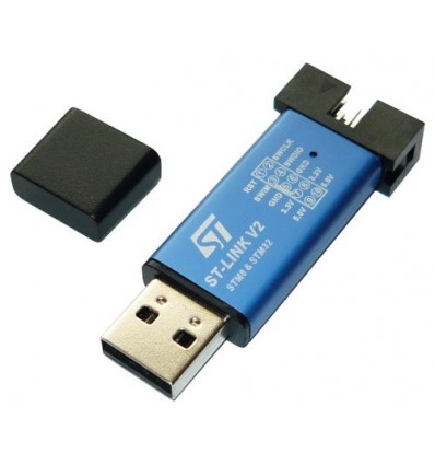
> :warning: To program the YJ-14015 MCUs you need an ST-Link v2 programmer, these can be found on eBay or Aliexpress for as little as 2$ shipped. See [picture below](#nordic-mcus-firmware).
##### Resistor values
If you want to customize your LEDs color or save a few bucks by ordering the LED all the same color you can refer to this section for choosing the correct resistor values. Otherwise you can refer to the [default configuration](#default-configuration).
There are two sets of resistor that you need for the receiver.
- The voltage divider resistors (`R1`, `R2` and `R3`): anything between 1.5k Ohm and 4.7k Ohm is good.
- The LEDs resistors (`R4`,`R6`,`R7` and `R8`): see the following table.
| LED color | Vf | Suggested resistor value |
|-----------|------|--------------------------|
| Red | 1.7V | 330 Ohm |
| Yellow | 2.1V | 330 Ohm |
| Blue | 3.2V | 220 Ohm |
| Green | 2.2V | 330 Ohm |
| White | 3.6V | 220 Ohm |
Depending on the color you choose to use you should use the resistor listed above.
#### Default configuration
Here you can find the default configuration for the receiver assembly.
| Label | Component |
|-------|-------------------|
| D1 | Red LED |
| D2 | Blue LED |
| D3 | Green LED |
| D4 | White LED |
| R4 | 330 Ohm resistor |
| R6 | 220 Ohm resistor |
| R7 | 330 Ohm resistor |
| R8 | 220 Ohm resistor |
| R1 | 1.5k Ohm resistor |
| R2 | 1.5k Ohm resistor |
| R3 | 1.5k Ohm resistor |
## Transmitters Assembly
Assembly steps:
- Solder components to PCBs (you can proceed in no particular order):
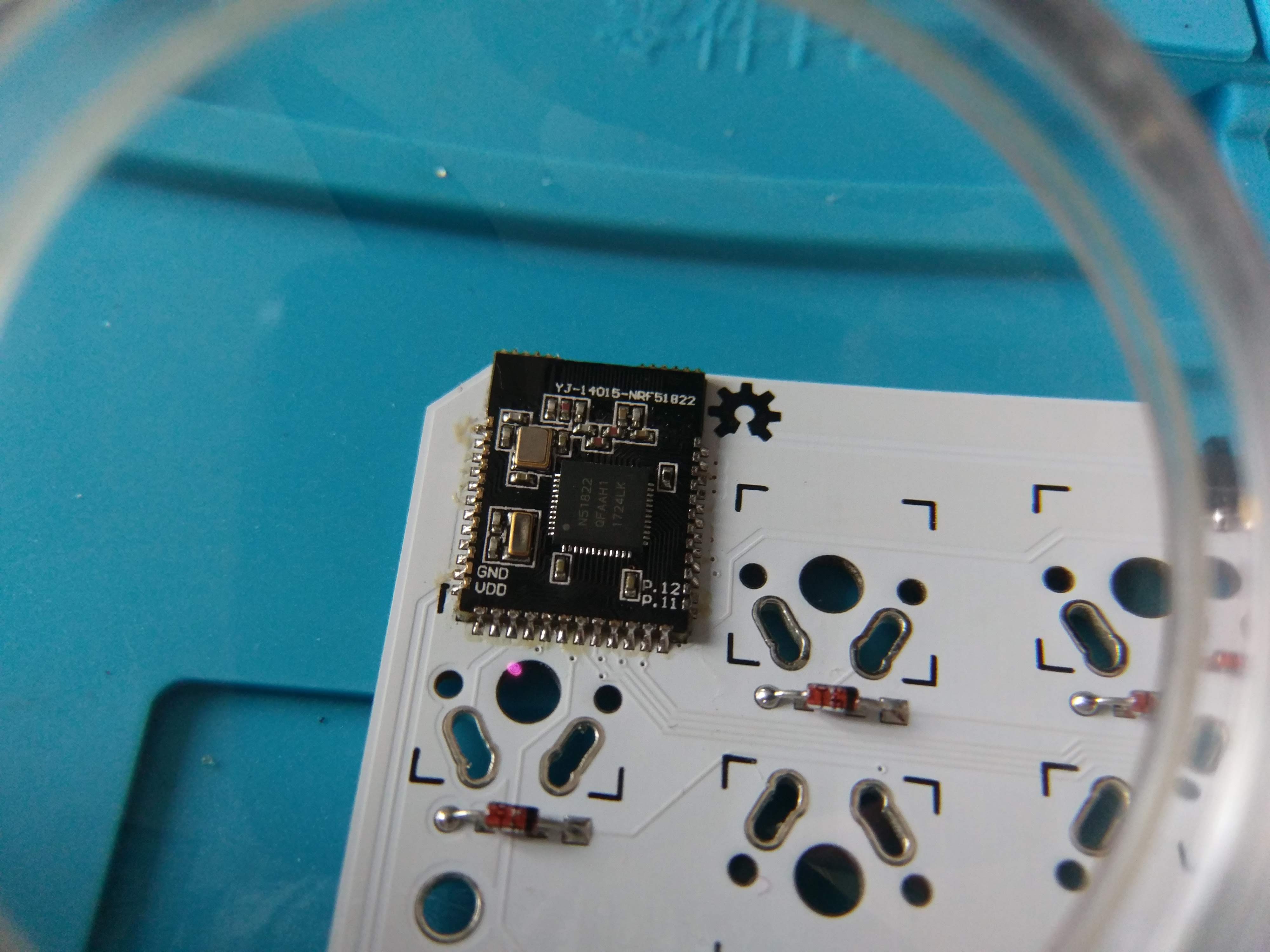
1. Solder the YJ-14015.
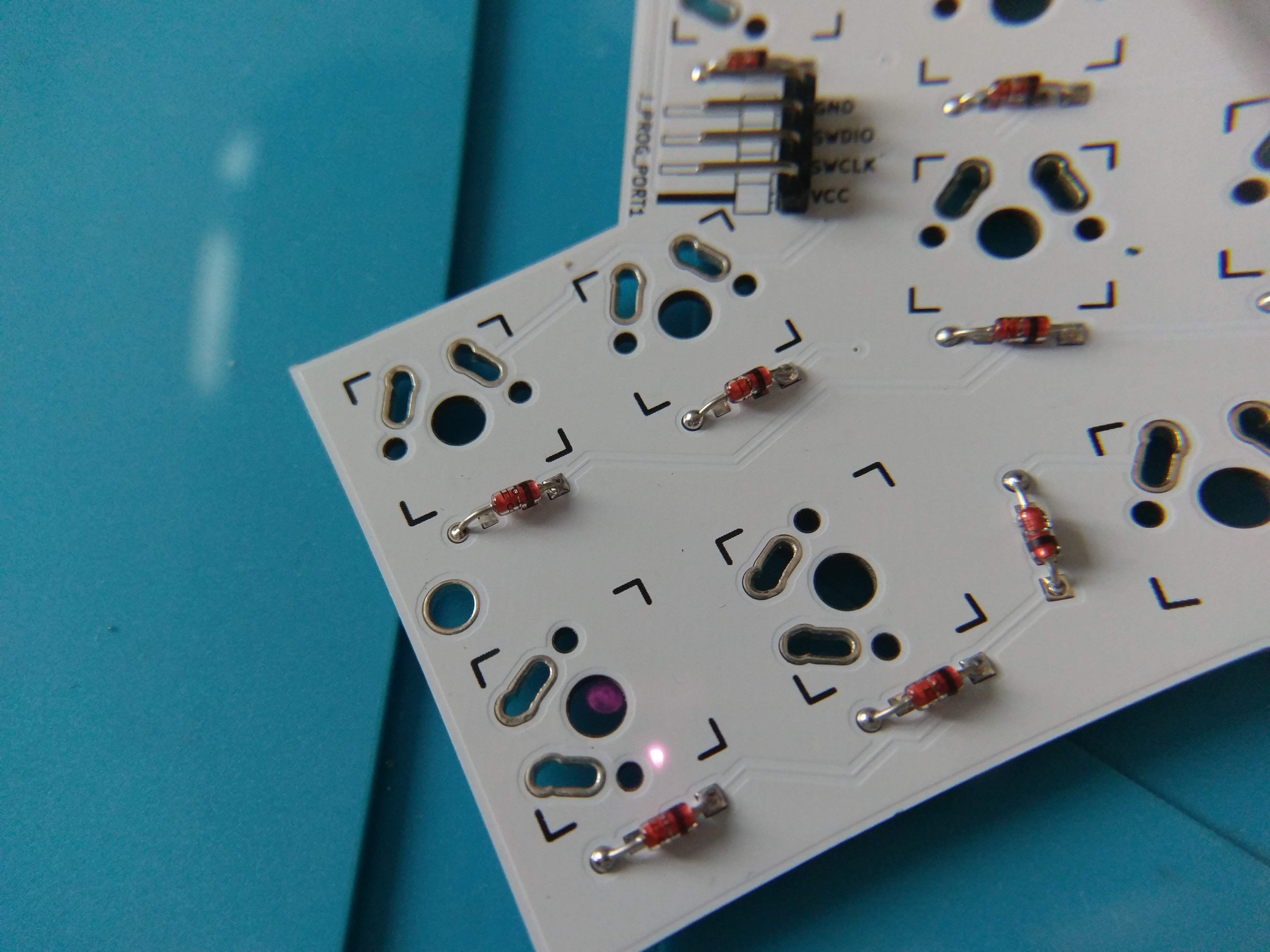
2. Solder 1N4148 diodes.
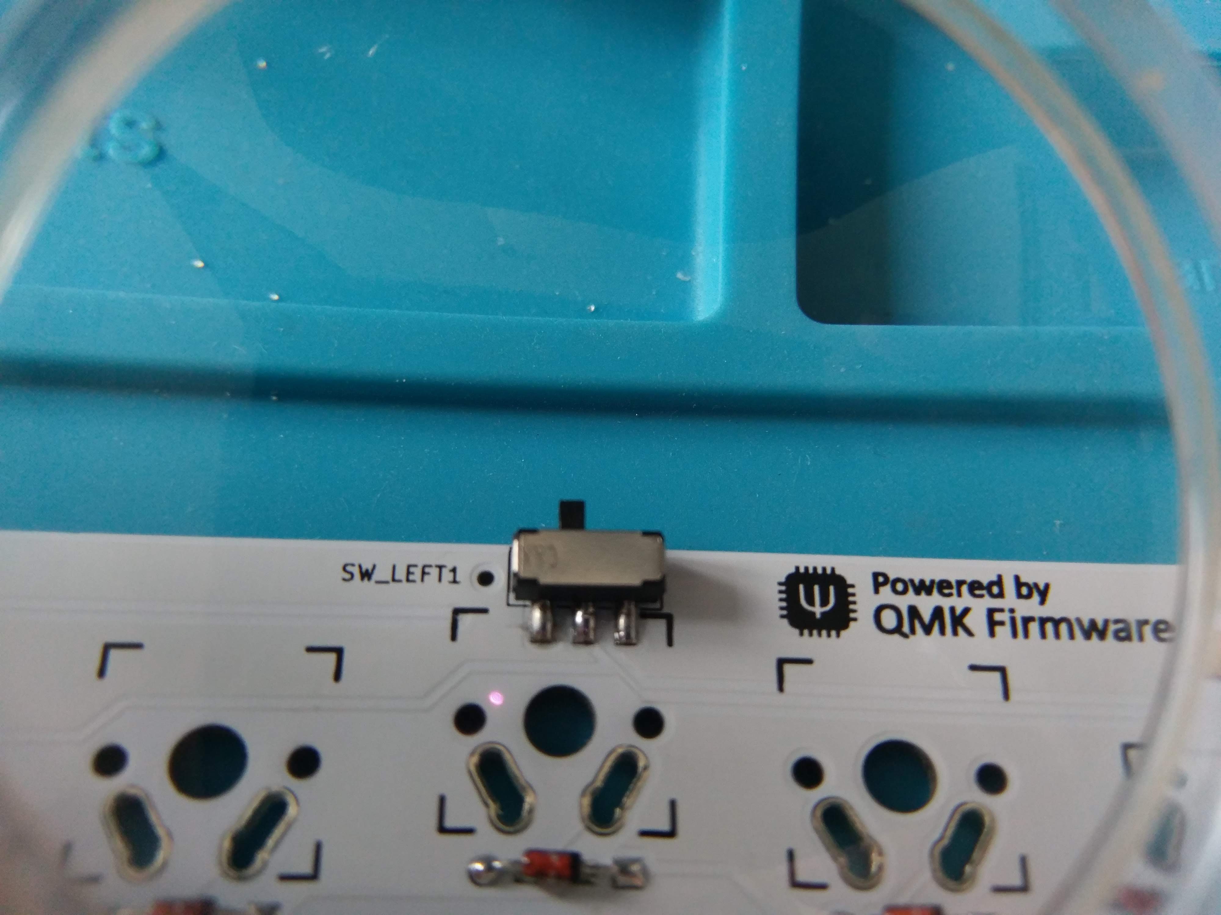
3. Solder slider switches.
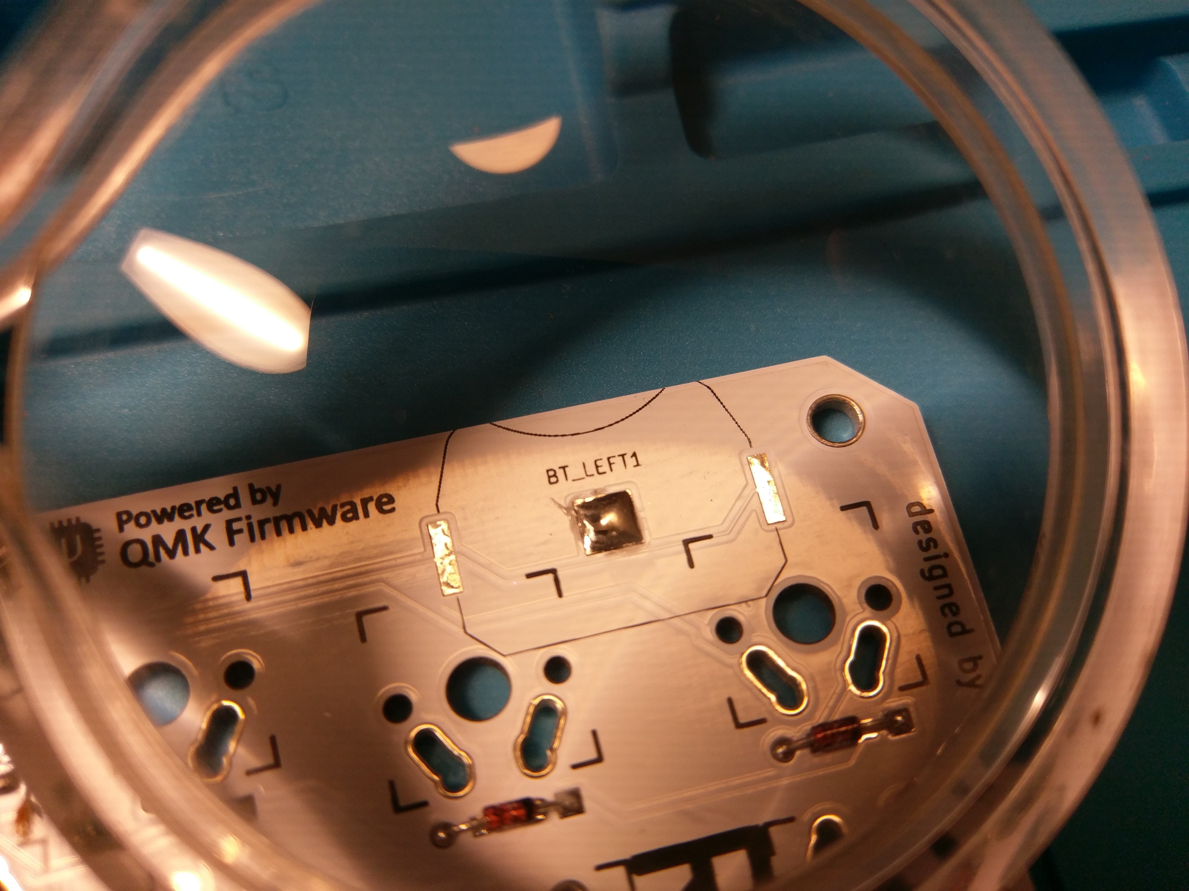
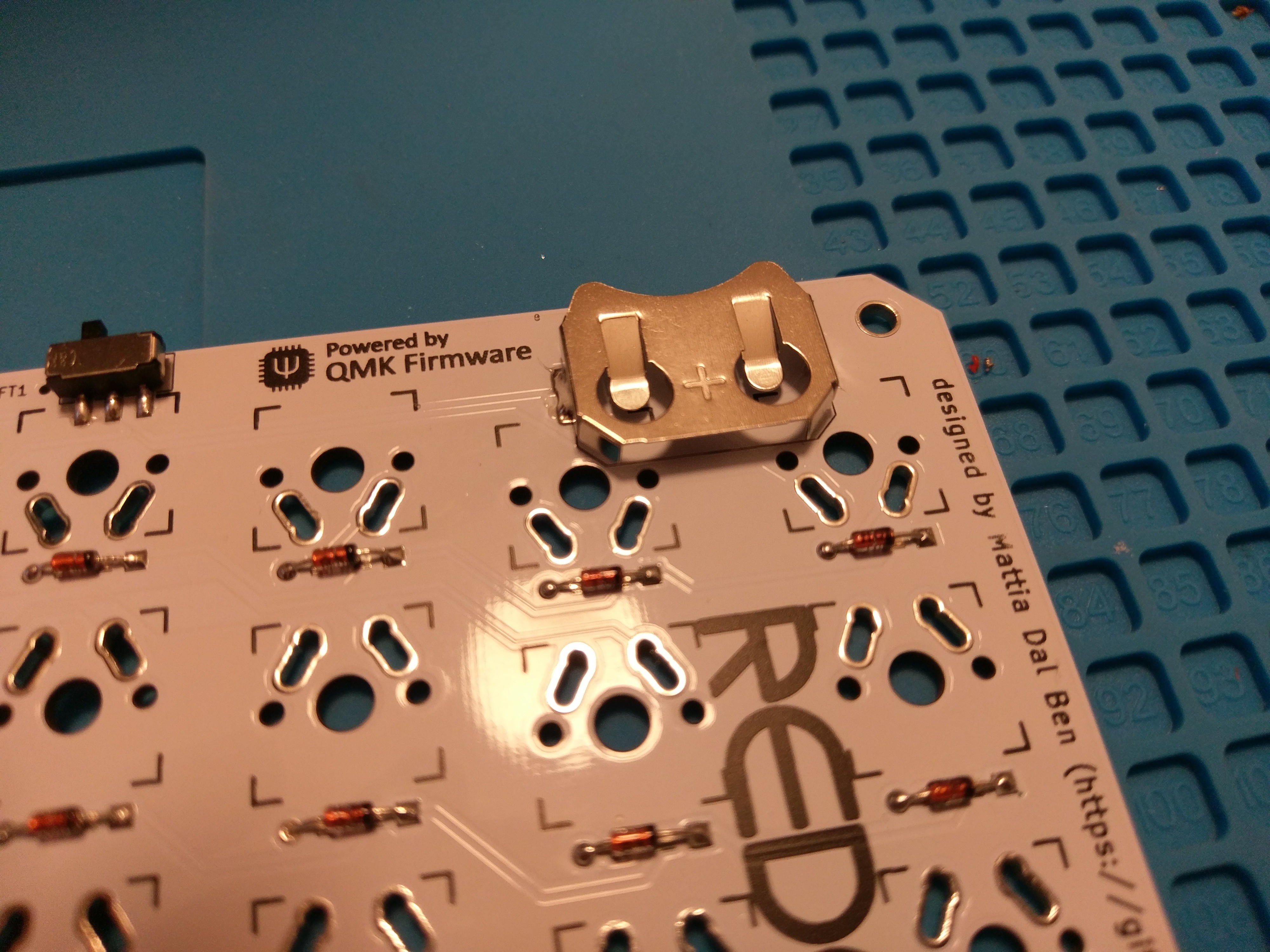
4. Solder the battery holders. *Note*: Some solder is needed on the ground pad to contact properly with the battery. See [picture below](#battery-holder-installation-detail).
5. Solder the programming headers.
- Fit the PCBs inside their cases.
- Add the switches to the plate.
- Solder switches to the PCB.
- Add the CR2032 batteries.
- Program the MCUs.
- Close the case.
##### Programming headers detail:

##### MCUs detail:
##### Slider switch detail:
##### Diodes installation detail:
##### Battery holder installation detail:
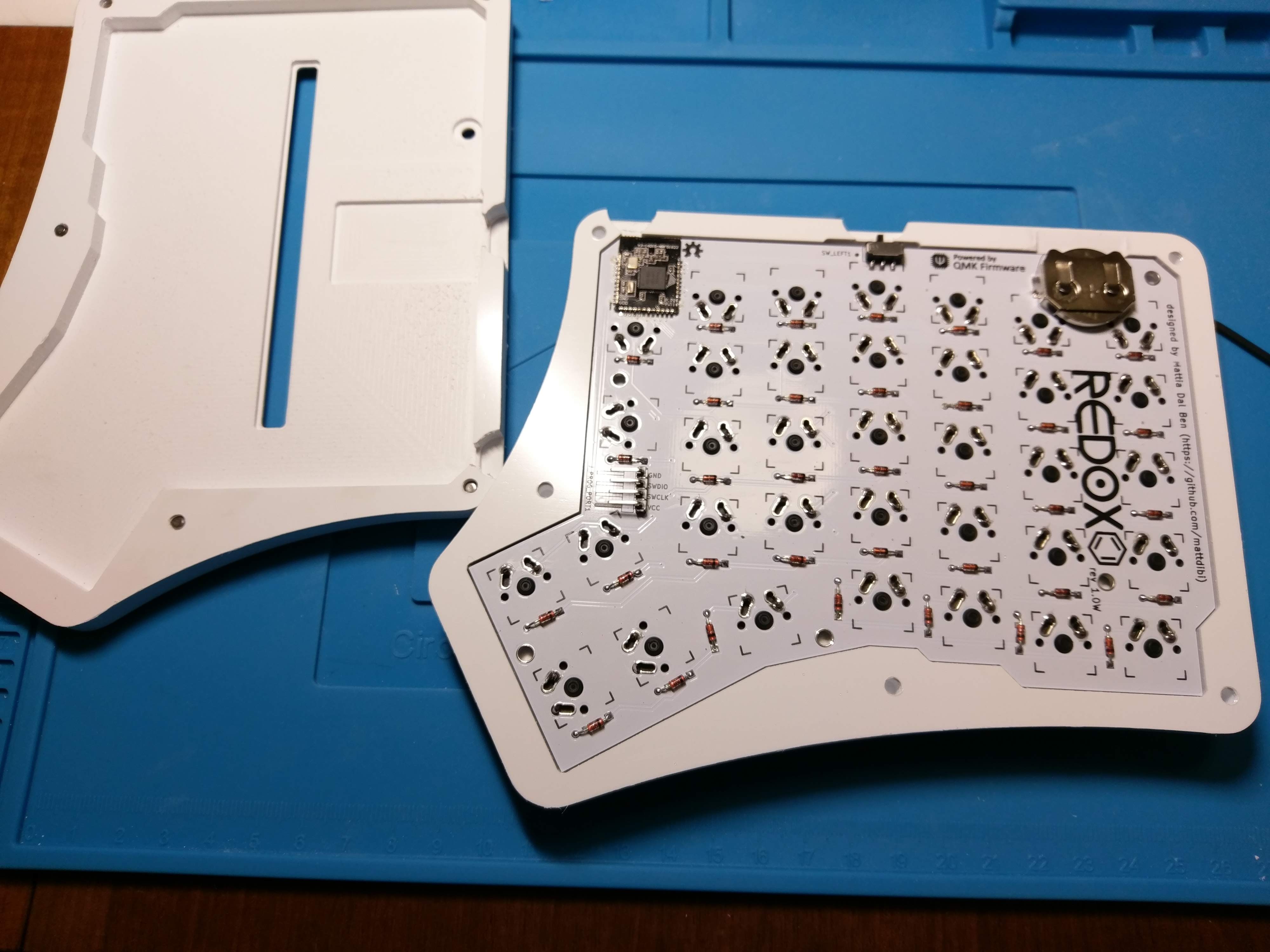
##### Left and right hand completed assembly:
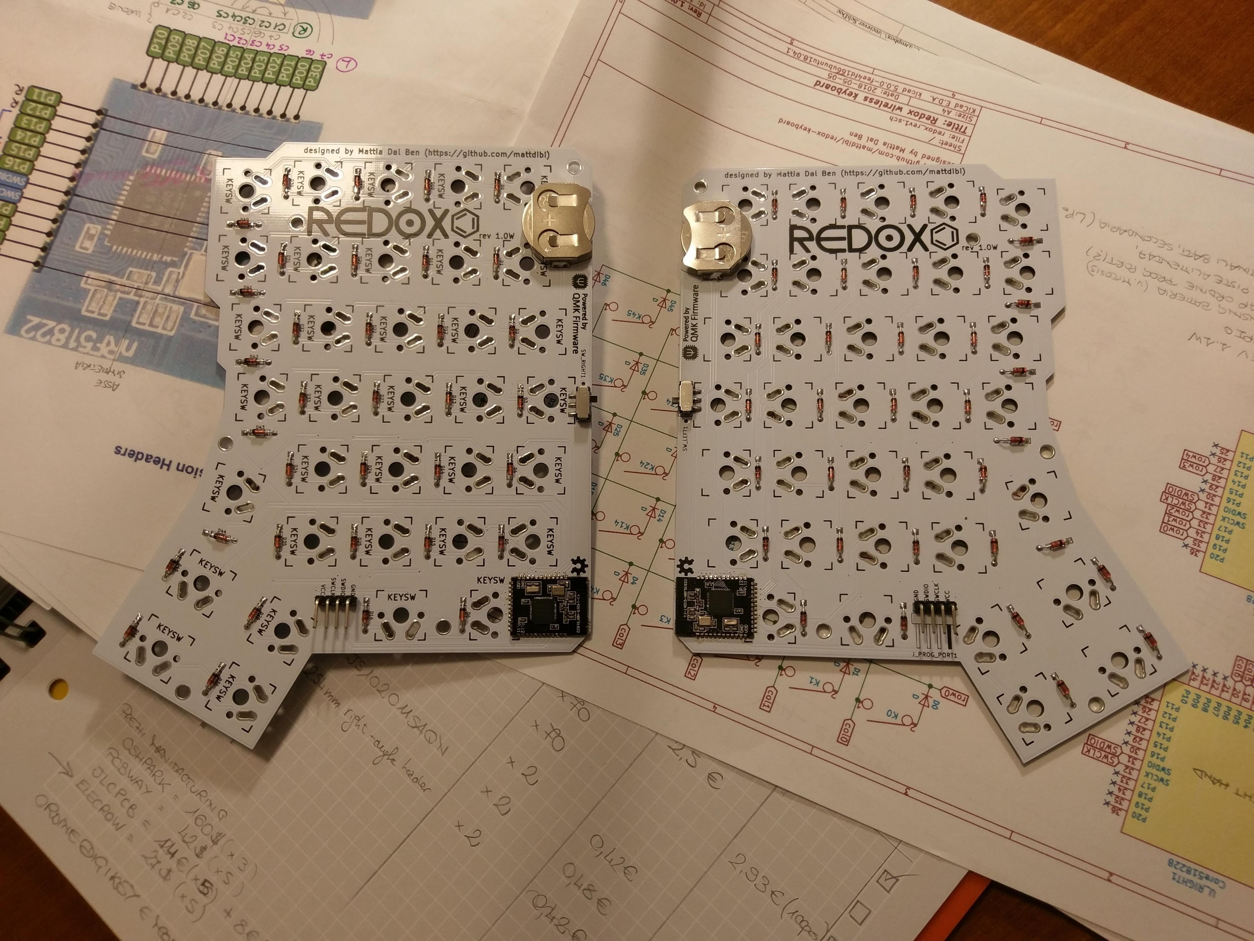
##### Assembled PCB:
## Receiver Assembly
The receiver assembly is pretty straightforward, you can install the components in any order you like with the exception of the YJ-14015: it should be installed **after** the right angled header (PROGR_HEADER1). Suggested assembly order:
1. Solder D1, D2, D3 and D4 LEDs. See [image](#leds-installation-detail) for orientation.
2. Solder R4, R6, R7 and R8 resistors.
3. Solder R1, R2 and R3 resistors.
4. Solder the AMS1117.
5. Solder the Arduino Pro Micro headers.
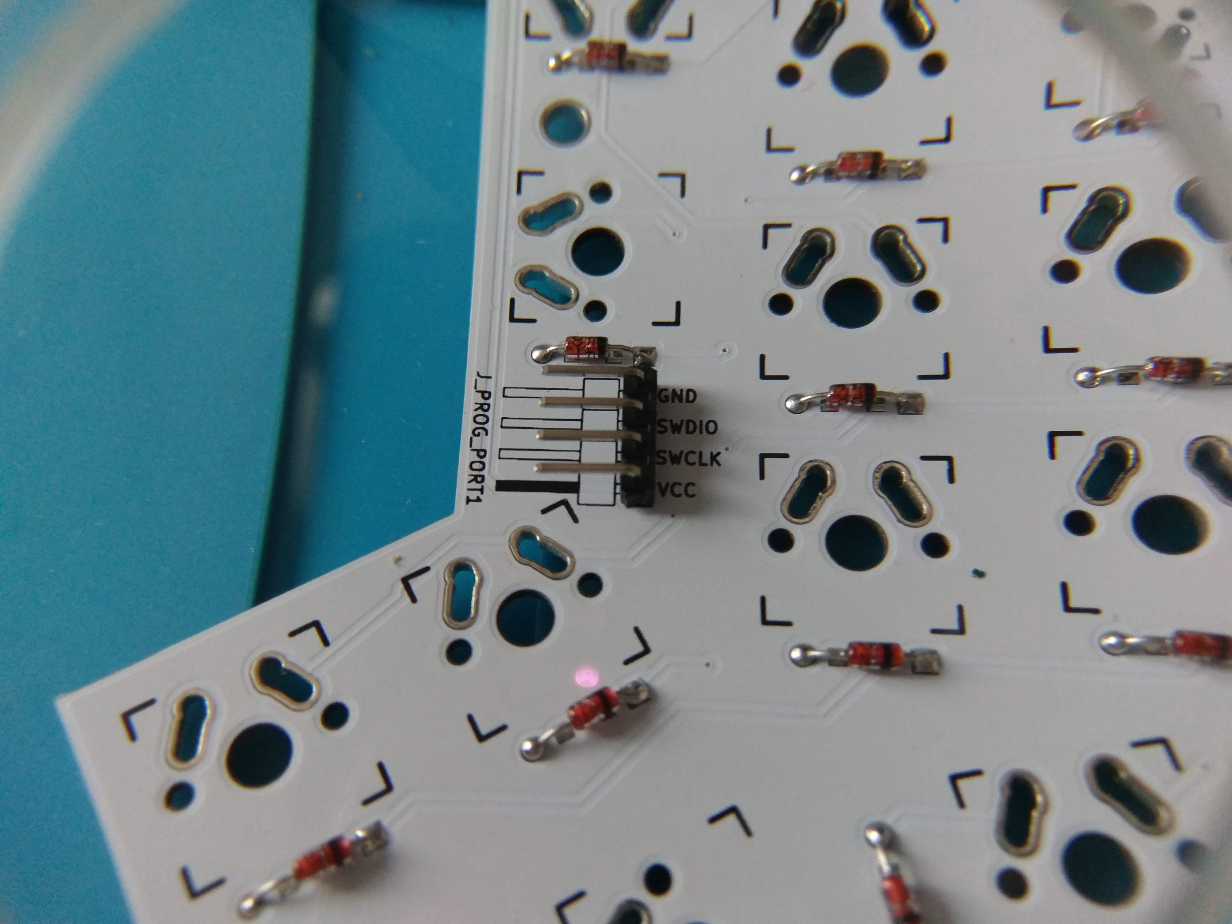
6. Solder the programming headers. I suggest you to cut the excess of the header **before** soldering the headers. You should stay as flush to the PCB surface as possible since the controller will be soldered above the headers. Use some masking tape to help you keep the header in place while soldering.
7. Solder the YJ-14015. I suggest you to glue it in place or use some masking tape to help you during soldering.
8. Upload the firmware and you're done.
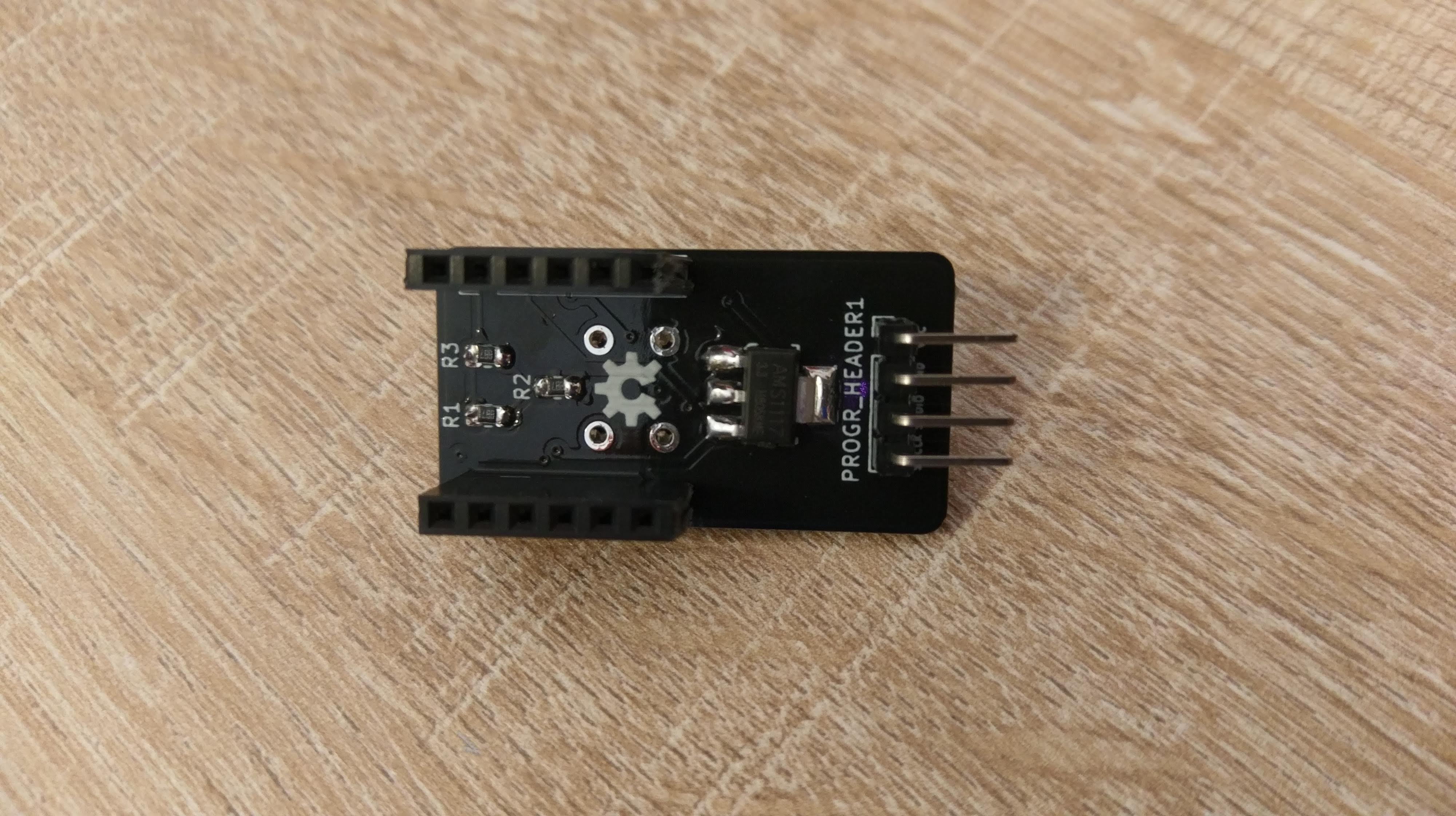
##### Assembled PCB, front:
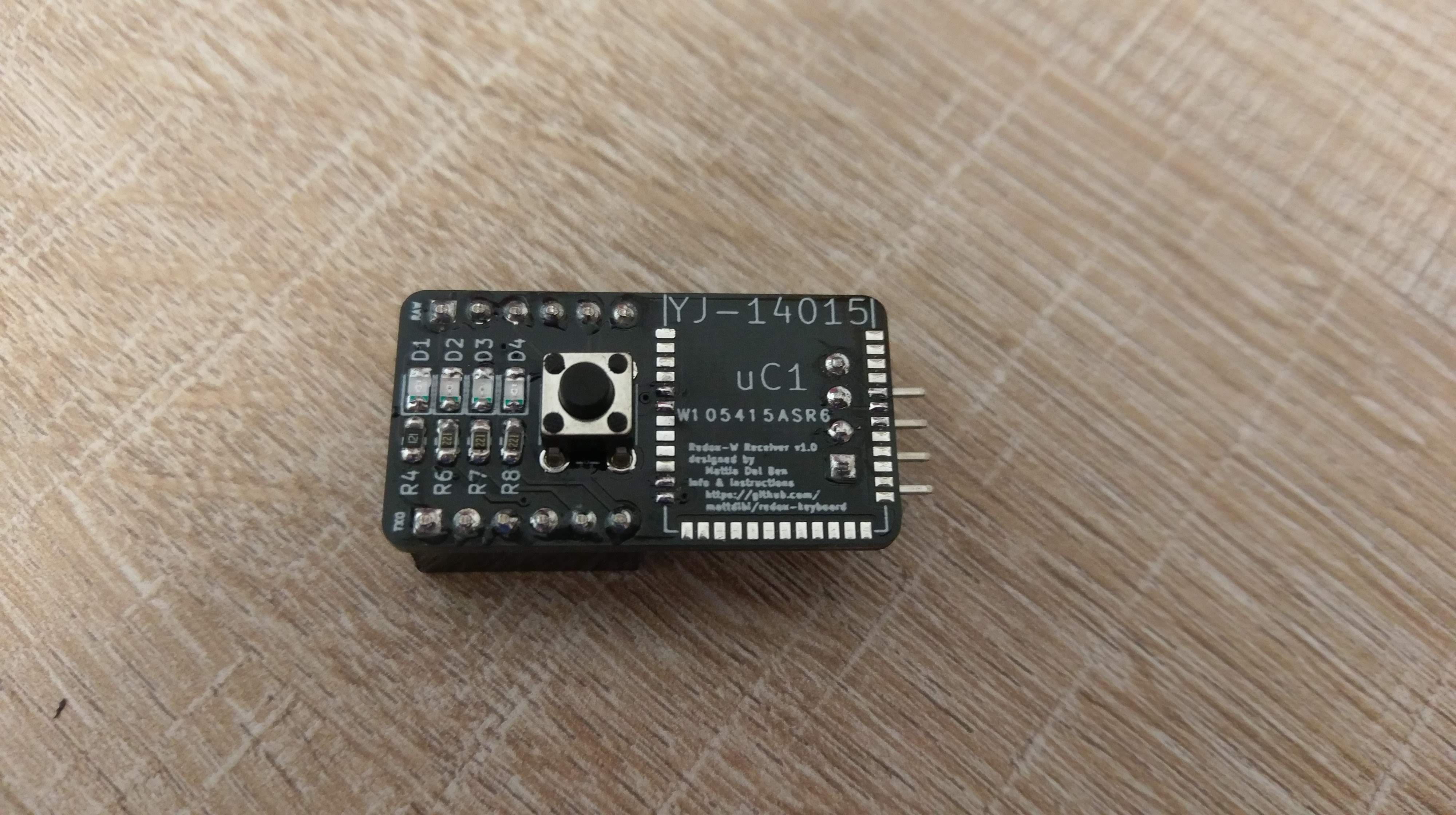
##### Assembled PCB, back:
##### LEDs installation detail:
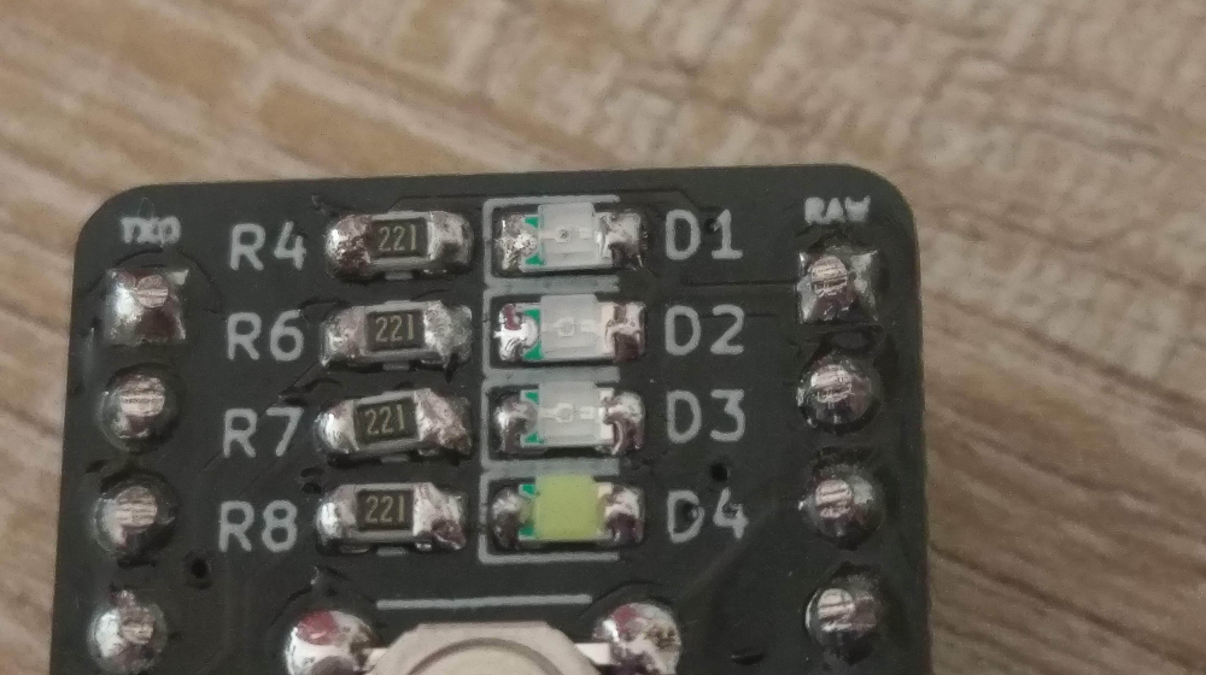
> :information_source: Please note that here I installed 220 Ohm resistors because I used only blue and white LEDs as I only had those laying around. You should use the resistor values suggested [here](#resistor-values) or follow the [default configuration](#default-configuration).
## Firmware
You'll need to upload the firmware to the corresponding MCUs as per the following diagram:
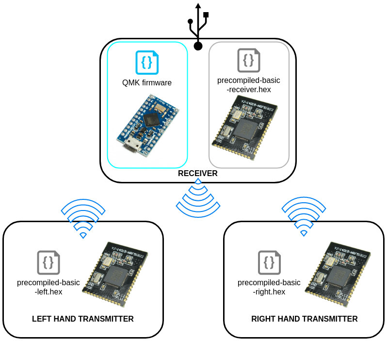
Note that you'll need to upload the firmware for the YJ-14015 only once. Everything related to the keymap is handled by the Arduino Pro Micro and QMK Firmware, that's what you will need to modify to update the keymap.
### Step-by-step firmware upload guide
#### Arduino Pro Micro Firmware upload
Let's start by uploading the QMK firmware on the Arduino, this will help us in diagnosing problems early on. The Redox uses QMK for its firmware, follow the QMK installation instructions [here](https://docs.qmk.fm/#/getting_started_build_tools), then compile and burn the firmware as follows:
```sh
$ cd path/to/qmk_firmware
$ make redox_w:default:avrdude
```
You can find the code for the Redox here: [QMK - Redox Wireless keyboard](https://github.com/mattdibi/qmk_firmware/tree/redox_wireless/keyboards/redox_w).
In the [Redox Wireless Keyboard firmware repository](https://github.com/mattdibi/redox-w-firmware/tree/master/precompiled) I added some pre-built hex files with the default keymap for testing purpose.
#### Nordic MCUs Firmware upload
You'll need only to flash the pre-built `.hex` files to the corresponding MCUs, for this you'll need an STLinkV2 debugger.
*Note*: Tested on Ubuntu 16.04 and 18.04 but you should be able to find alternatives on all distros.
##### Setup
###### Install OpenOCD (Open On-Chip Debugger)
```sh
sudo apt install openocd
```
###### Download the repository
Open a terminal and download this repository wherever you want. We'll need the `redox-w/firmware` folder content.
```sh
git clone https://github.com/mattdibi/redox-keyboard.git
```
or
```sh
wget https://github.com/mattdibi/redox-keyboard/archive/master.zip
```
###### Install the udev rules
```sh
cd path/to/repository/redox-keyboard/redox-w/firmware/
sudo cp 49-stlinkv2.rules /etc/udev/rules.d/
```
##### Programming the receiver
###### Hook up the receiver
Hook up the ST-Link debugger to the receiver board you assembled without the Arduino. You need to connect only the `VCC`, `GND`, `SWDIO` and `SWCLK` pins of the receiver board like this:
| ST-Link Debugger | Receiver board |
|------------------|----------------|
| 3.3V | VCC |
| GND | GND |
| SWCLK | SWCLK |
| SWDIO | SWDIO |
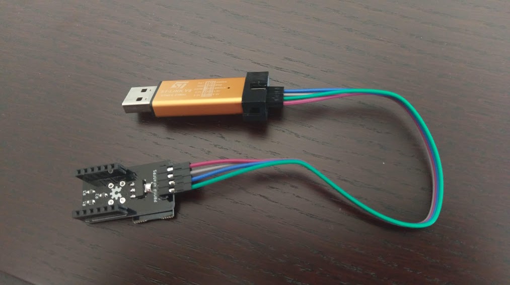
Then plug in the ST-Link debugger into your PC.
###### Launch a OpenOCD server session
In a new terminal window launch an OpenOCD server session by issuing the following command:
```sh
openocd -s /usr/local/Cellar/open-ocd/0.8.0/share/openocd/scripts/ -f interface/stlink-v2.cfg -f target/nrf51.cfg
```
This should give the following output:
```sh
Info : nrf51.cpu: hardware has 4 breakpoints, 2 watchpoints
```
Leave this terminal window open.
###### Receiver firmware flashing
We can now issue the flashing commands. Open a terminal in the redox-w firmware folder.
```sh
cd path/to/repository/redox-keyboard/redox-w/firmware/
```
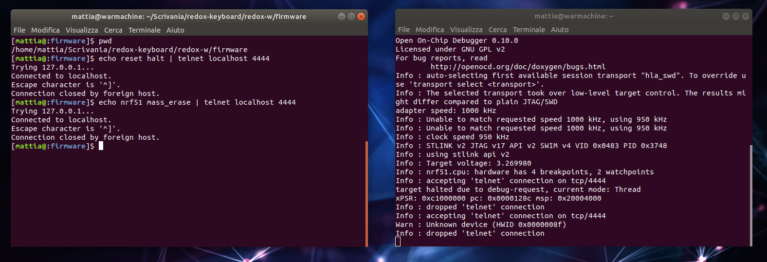
From the factory, these chips need to be erased:
```sh
echo reset halt | telnet localhost 4444
echo nrf51 mass_erase | telnet localhost 4444
```
You should be seeing some movement in the OpenOCD terminal window, and you desktop should be looking somewhat like this:
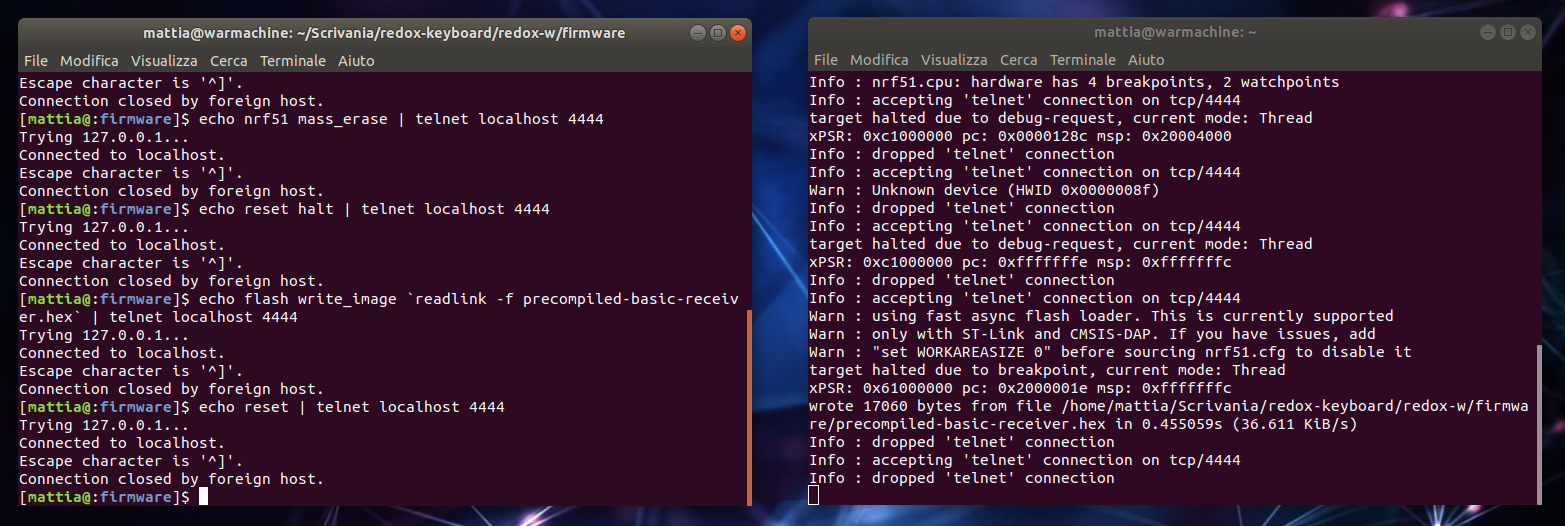
Now we can upload the receiver firmware onto the MCU.
```sh
echo reset halt | telnet localhost 4444
echo flash write_image `readlink -f precompiled-basic-receiver.hex` | telnet localhost 4444
echo reset | telnet localhost 4444
```
You should be looking at something like this:
Now close the OpenOCD session (use `Ctrl-C`) and you're done with the receiver. Repeat these steps for the two halves of the keyboard and you should be set.
##### Programming the two halves
###### Hook up the transmitter
Hook up the ST-Link programmer with the transmitters using the programming pins, and plug the debugger in you PC.
Start a OpenOCD session as seen above and start flashing the firmware.
###### Left hand firmware flashing
From another terminal window issue the following commands. Again from the factory, these chips need to be erased:
```sh
echo reset halt | telnet localhost 4444
echo nrf51 mass_erase | telnet localhost 4444
```
Upload the left hand firmware.
```sh
cd path/to/repository/redox-keyboard/redox-w/firmware/
echo reset halt | telnet localhost 4444
echo flash write_image `readlink -f precompiled-basic-left.hex` | telnet localhost 4444
echo reset | telnet localhost 4444
```
###### Right hand firmware flashing
After having hooked up the right hand to the ST-Link debugger and started a new OpenOCD session we can upload the right hand firmware.
Again from the factory, these chips need to be erased:
```sh
echo reset halt | telnet localhost 4444
echo nrf51 mass_erase | telnet localhost 4444
```
Upload the right hand firmware.
```sh
cd path/to/repository/redox-keyboard/redox-w/firmware/
echo reset halt | telnet localhost 4444
echo flash write_image `readlink -f precompiled-basic-right.hex` | telnet localhost 4444
echo reset | telnet localhost 4444
```
Congratulations! You flashed the Redox-W firmware.
## Battery usage
I got the current consumption for the transmitters using a shunt resistor (10 Ohm) and an oscilloscope during transmission.
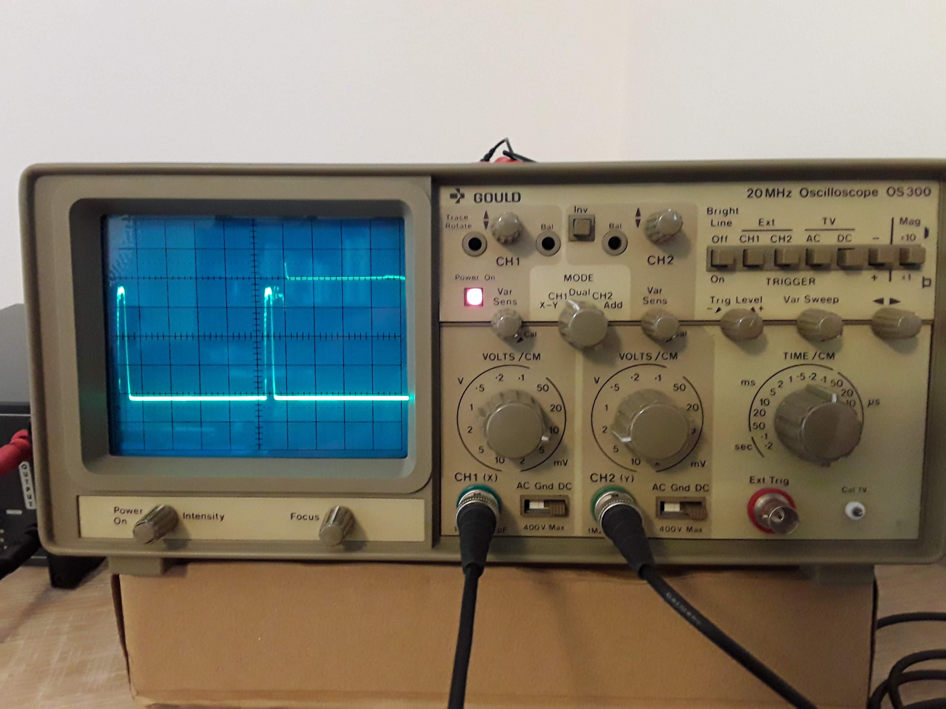
Data:
- Current peak of 5mA (Irun) and 50us duration (trun)
- Idle consumption of 2.7uA (Iidle) between peaks, that is 950us duration (tidle).
We can then calculate the average current consumption during typing (Iavg) using the following:
 Knowing that the CR2032 battery is rated for 220mAh we get:
 **TLDR**: We can expect **at least 880 hours** of continuous typing on the keyboard before needing to change the batteries. Keep in mind that when you're not typing (500ms without key presses is the time interval needed for the keyboard) the transmitters go into deep sleep mode and draw only 2.7uA. So for an everyday use (4 hours a day of continuous typing) you can expect a battery life of at least a year. Obviously your mileage may vary.